 kutluhan_aktar
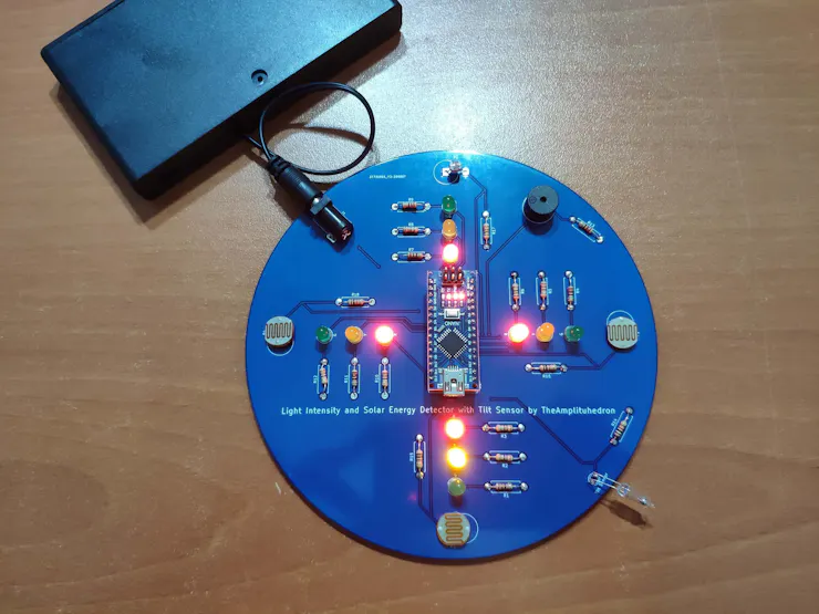
After running the code to calculate solar energy with light intensity values gathered by 10mm photoresistors, I conducted experiments with batteries and my solar panel to determine thresholds for performance levels of solar charging: Low, Moderate, High. And, to show the performance levels, I used different LED colors - red (Low), yellow (Moderate), green (High) - for each direction.
Not surprisingly, it is crucial to place the device perpendicular to detect light intensity accurately, so I used a tilt sensor (mercury sensor) to check if the device moves into a tilted position. And, to notify the user, when the device moves into a sloping position, I added a buzzer to the device.
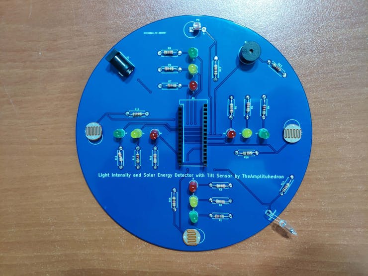
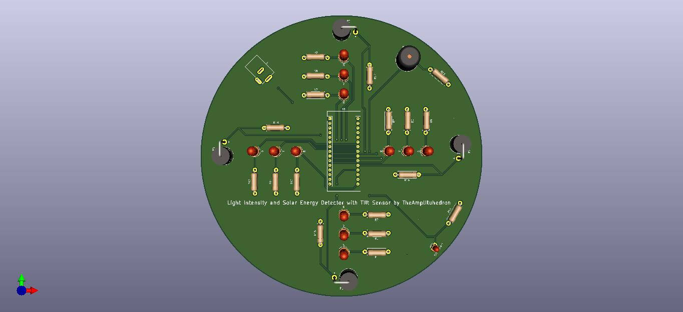
After completing my design on a breadboard and testing the code, I designed a PCB (Light Intensity and Solar Energy Detector with Tilt Sensor) with a unique circular shape to create a flexible and easy-to-use device supporting four directions.
Huge thanks to JLCPCB for sponsoring this project.
Step 1: Designing and Soldering the Light Intensity and Solar Energy Detector with Tilt Sensor PCB
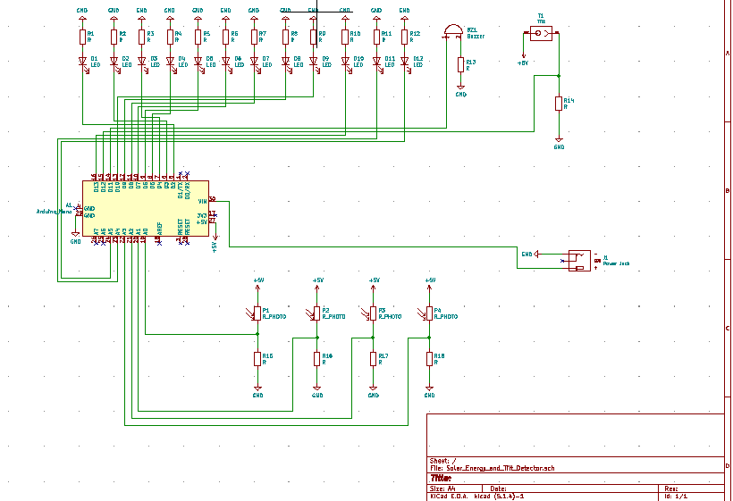
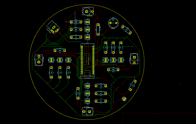
I designed the Light Intensity and Solar Energy Detector with Tilt Sensor PCB by using KiCad. I attached the Gerber file of the PCB below, so if you want, you can order this PCB from JLCPCB to use your solar panels more efficiently and sustainably as I did :)

First of all, by using a soldering iron, I attached headers, 220Ω resistors, 1K resistors, 10mm photoresistors, the power jack, 5mm red LEDs, 5mm yellow LEDs, 5mm green LEDs, buzzer, and the tilt sensor (mercury sensor).
Component list on the PCB:
A1 (Headers for Arduino Nano)
P1, P2, P3, P4 (10mm Photoresistors)
Buzzer (Buzzer)
Tilt Sensor (Tilt Sensor)
R (5mm red LEDs)
Y (5mm yellow LEDs)
G (5mm green LEDs)
R1, R2, R3, R4, R5, R6, R7, R8, R9, R10, R11, R12, R13 (220Ω resistors)
R14, R15, R16, R17, R18 (1K Resistors)
J1 (Power Jack)


Step 2: Calculating Solar Energy Approximately
[ E = A * r * H * PR ] is the formula I used for calculating the magnitude of solar energy approximately, where:
A is the area of the solar panel,
r is the efficiency,
H is the average solar radiation,
and PR is the performance ratio or coefficient (generally 0.75).
// Define the solar panel (SP) specifications which differ amid different brands. So, change these variables with that of your solar panel. #define SP_area 0.0088 #define SP_efficiency 6.2 #define SP_coefficient 0.75 float Solar_Panel_Energy(float Area, float Efficiency, int Radiation, float Coefficient){ // Calculate the possible magnitude of solar energy by using the light intensity values as a substitute for radiation. float Energy = Area * Efficiency * Radiation * Coefficient; return Energy; }
Do not forget to change solar panel specifications - area, efficiency, and performance ratio - which may differ amid solar panel brands.
To calculate the possible magnitude of solar energy, I used light intensity values as a substitute for solar radiation in the formula.
Of course, this method does not provide exact solar energy values but an indicator to determine thresholds (Low, Moderate, High) for detecting solar charging performance in a given direction.
Note: I determine the thresholds for each level by conducting tests with my solar panel: I observed time passed in given light intensity and estimated solar energy values to full-charge a 3.7V LiPo battery.
Step 3: Programming the Arduino Nano
- Define indicators (red, yellow, green) for each direction.
- Define LDR pins for each direction to gather light intensity values.
- Define the buzzer pin and the tilt sensor pin.
- Define the solar panel (SP) specifications, which differ amid different brands. So, change these variables with that of your solar panel.
- Define thresholds by experimenting.
- In the get_Light_Intensity() function, gather light intensity data from photoresistors.
- In the Tilt() function, get...

 Domen
Domen
 ASHUMHRPROJECTS
 Wasim Sahu
Please feel free to leave a comment here if you have any questions or concerns regarding this project :)