Close
0%
0%

"Desk Accessory" CNC Milling Machine

Lots of "Desktop CNC" machines can fit on a desktop. But do they fit _on_your_desk_? Like, between the stapler & paper tray?

Similar projects worth following
Developing fancy packaging for a usefully capable desktop CNC milling machine with footprint & cost more like a stapler than a desk.

Ok, "stapler" is a little dramatic. Just a little. Footprint smaller than a paper tray for sure.

Companion projects (and Hackaday Prize finalists):
"I have access to a 3d printer": https://hackaday.io/project/192074
"I have access to a laser cutter": https://hackaday.io/project/174370

Like this...

...as of April 2024


Check out...

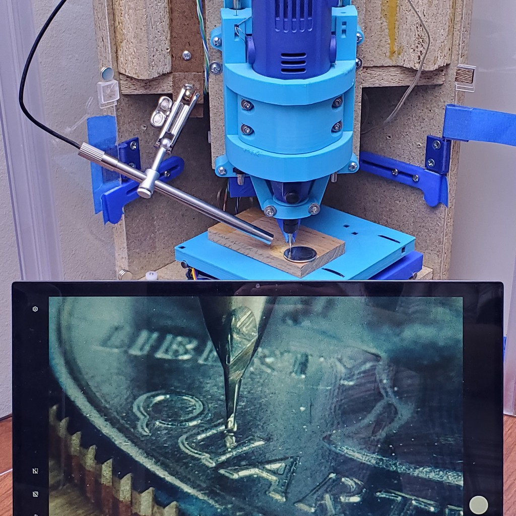
this photo gallery of work examples.


Companion projects...

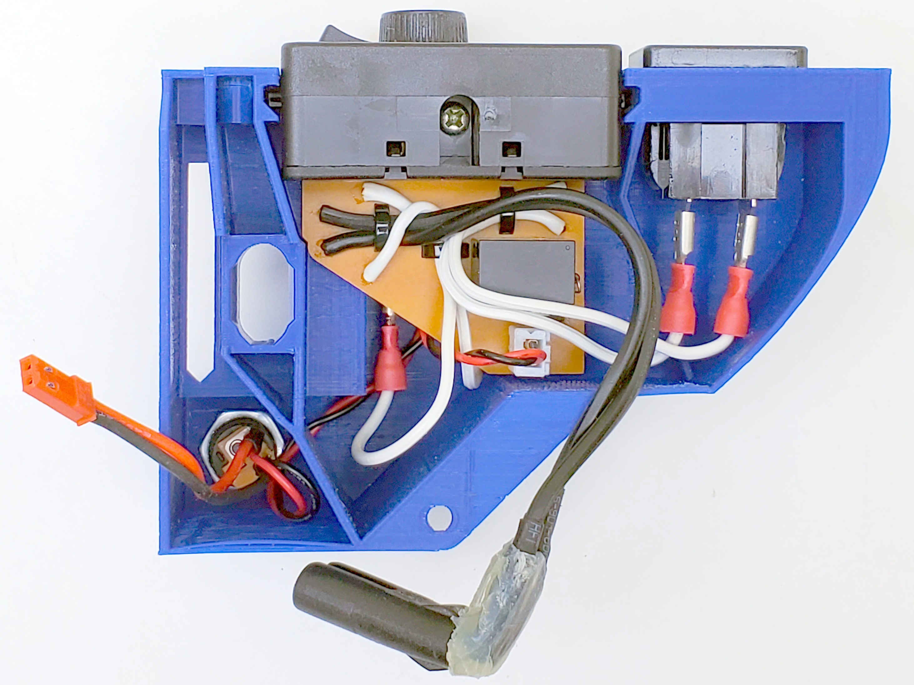
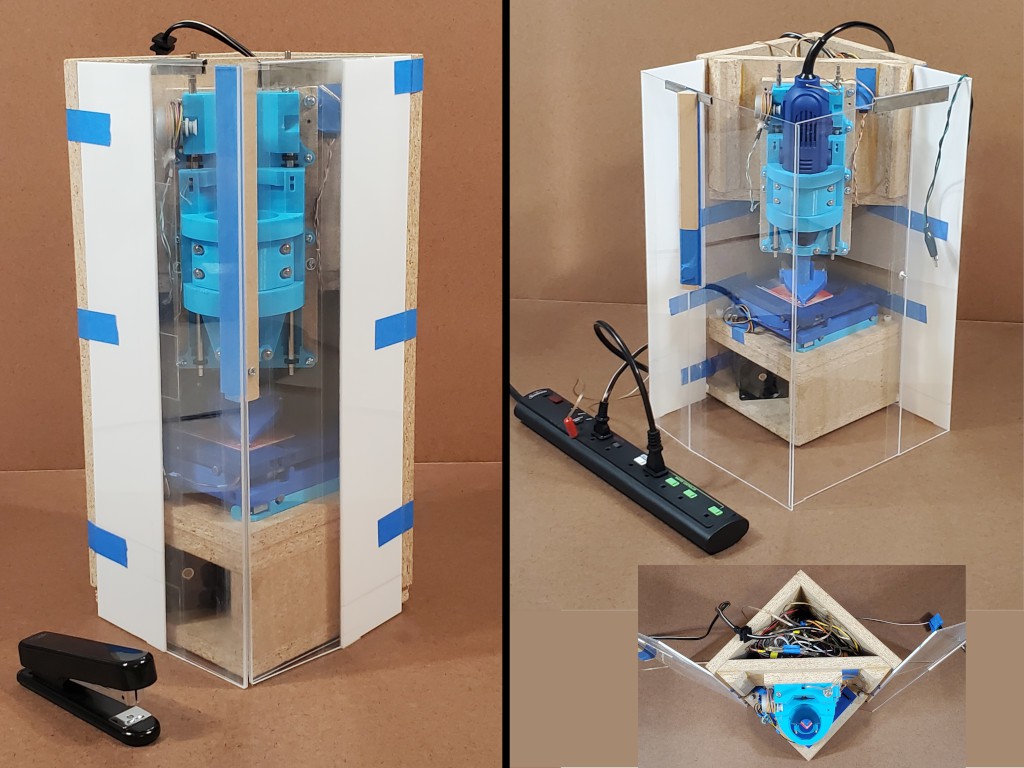
#Minamil 3dp: another minimal CNC mill and #Minamil 2dc: a minimal CNC mill  develop the CNC mechanics. Neither of those projects require this project. This project focuses on fancy packaging, integration, and compactness that I like for my use case.


Sparse here; more in the Log entries

This page used to have more "details", but they had become unhelpfully stale details, so I squashed it down to this until I get around to writing up a freshtastic new Details page. 

  • sane(ish) AC achieved, I think -- and bootstrap circuit board

    Paul McClay6 days ago 0 comments

    Log catch-up campaign: closing in on caught up so I can get back to work getting ahead of logs again.


    So I've got this box with a few compartments and a plan to keep all the AC power wiring in the top compartment in order to separate "high" voltage from low voltage DC.

    This iteration of the AC stuff seems to be at least ok. For me; for now.


    I've made this harder for myself by chasing conflicting  ̶r̶e̶q̶u̶i̶r̶e̶m̶e̶n̶t̶s̶  aspirations.

    And I don't know jack about "best practices" for making stuff with line voltage AC in it. If I may quote myself from elsewhere:

    Dear reader: this is random Internet "content" by an unqualified author for entertainment only. Misuse of [mains AC] can kill you and burn your house, which may entail killing other people. How to do anything with [AC] other than what the label says without burning stuff or killing people is beyond the scope of this writeup. Consider this first-person account as a pre-staged footnote for my eventual Darwin Award and not as instructions for anything you should do.

    For AC stuff, I wanted

    • onboard DC supply
      • inlet - because I wanted a clean box exterior without a hardwired cord (hardwired out the top was an option)
      • fuse
      • switch
    • relay-switched outlet for "spindle"
      • logic-switched relay
      • US ungrounded, polarized outlet (NEMA 1-15R)

    Not rocket science.

    I figured that could fit in something less than all of the volume of the upper compartment, leaving some room to stash stuff like the power cord and most of the dremeloid cord. I started out thinking that would get done with a simple partition to divide the space into AC (closed) and storage (open). But I didn't come up with a simple partition that seemed like a good use of the space. Which got me thinking about a less simple, more conformal, probably 3d printed, enclosure for the AC stuff inside that compartment. Which lead to greed for the most space for storage which meant fitting the AC stuff into the least space without crowding stuff that shouldn't touch or mashing soft insulation between hard parts.

    For this iteration, I decided to use a double-insulated power brick with a C8 inlet for the benefits of having that already robustly enclosed/insulated and also the more compact power cord vs the common grounded 15A "IEC" type (i.e. C13) cord.

    The Unified AC Widget fits into the corner with the power supply.

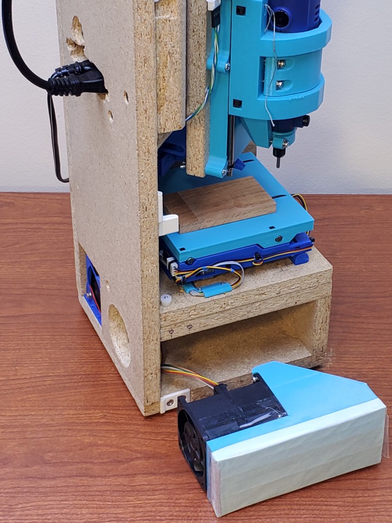
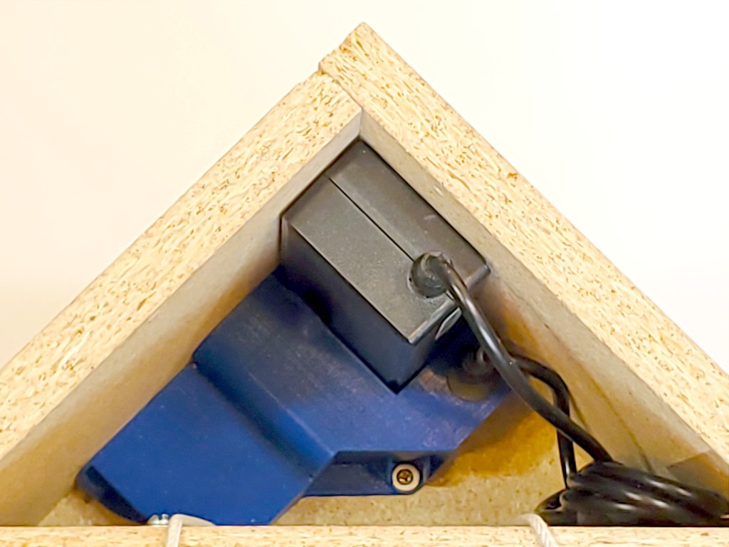
    The DC-out cord from the supply could be cut down to the minimum needed to make the connection.


    Cutouts in the back wall of the box expose the interactive bits.


    Stuff inside is compact without crowding.

    In addition to the inlet/outlet/fuse/switch out the back, this includes a  ̶b̶u̶t̶c̶h̶e̶r̶e̶d̶  right-angle C7 plug for the power brick, the red connector for 12VDC power down to the low voltage electronics & motors below, and the mostly hidden connector for the logic-level spindle enable signal coming back up. A second tap off the DC input jack feeds the relay coil, relying on the relay & trace separation on the circuit board for galvanic isolation from the high voltage stuff.

    If I build this configuration again, I'll get a right-angle plug for the power supply instead of farting around for the usual longer-than-expected time to make one with random dimensions.

    I should probably use insulated quick-connects or some such to make this unit itself more nearly something like double insulated.

    The circuit board helps compactify this and make it less of a crammed jumble of wires. That was something of a flag day for the project:

    Minamil mills a circuit board for itself

    I think that's kind of a thing. Part of the RepRap quest is (was, now that manufactured 3d printers are cheaper than BoM for DIY) the self-replicating machine that can make its own wiring. Here, with very little additional hardware, a 3d printer can print a very little...

    Read more »

  • am not electrician

    Paul McClay6 days ago 0 comments

    Continuing the log catch-up campaign...

    Earlier I mentioned keeping all the AC power wiring in the top of the frame, with intent to include a logic-switched power outlet for the "spindle".

    I'm going to mostly skip a couple iterations of "improving" that because:

    • it will expedite the log catch-up campaign, and
    • I'm not an electrician and sometimes do dumber stuff than usual that's easier to pretend didn't happen if I don't write Log pages about it.

    I did manage a first whack at fitting logic switched spindle power inside the box, so here's a few pix.


    Relay in the hot wire to a 1-15R outlet (the usual US two-prong polarized -- because that's the plug on my US market dremeloid).

    12VDC supply for the relay coil.

    Header pin for the "spindle enable" signal.

    Signal pin and FET for switching coil power (coil supply ground is common with the controller).

    Flyback diode because conventional wisdom says "flyback diode" -- no math attempted.

    Plated thru-holes de-plated for HV/LV isolation.

    Resistors under the FET: gate pulldown and a "protection" resistor because resistors between stuff and off-board connections make me feel gooder. Am not EE.

    Using a 3 position header and wiring the end pins together makes an easy non-polarized connection for coil power. I don't remember where I saw that trick. 

  • vent fan

    Paul McClay04/16/2024 at 05:37 0 comments

    After cutting stuff, I often see evidence of dust getting up to the top of the works...

    ...which I suppose indicates dust escaping entirely. For various reasons that wouldn't be great even I wasn't doing this inside the living space of my home.


    In the first semi-enclosed frame I knocked together, sucking air down into the enclosure and thru a filter worked well:

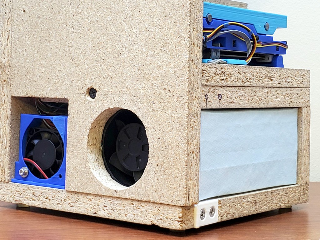
    Sticking a vacuum hose into the same space would probably work too -- to the extent that a given vacuum's filtration works -- but I'm going with running a vac briefly to clean up vs. continuously while operating (and I can use a cordless hand vac).


    That was good then, then I bumbled into building a new box. The new (i.e. current Apr 2024) box includes space for fan+filter, the fan, and fan power switched by the "coolant" signal. But no filter or exhaust opening.


    Lots of photos over the last ~year have shown this thing rattling around loose in that space:

    ... and sometimes in the accompanying text I've mumbled about that vent thing that's going to work great just as soon as I get it done.


    Now at last ... it is done!

    Only took most of a year.

    The idea is to keep dust from floating up out of the enclosure, or filtering out through various gaps, by sucking a sufficient flow of air in, mostly down through the open top.

    I could just stick a vacuum hose through the back of the box. But that wouldn't advance the all-in-one idea of this project.

    Some of the meanest stuff to spread around would be fine wood dust <citation needed>. Appropriately rated surgical masks <US rating - where did I note that already?> which purportedly can catch >98% of the mean stuff have become much more readily accessible post pandemic. And the planar filters occupy ~no volume. That's great. But they're not very free-flowing, and I want to pull lots of air through one. That's less great. Qualitatively, I figured pulling much air through one of those would require pulling much pressure drop behind the filter i.e. pushing much pressure gain across the fan. At a useful flow rate. That means a) power and b) coupling power to air with suitable pressure/flow characteristics.

    A mean fan

    After proving the function of the idea with a pair of mean fans that very much did not fit inside the box, a search for sufficient meanness in a sufficiently small package lead to discovery of "6076"-type integrated counter-rotating fan pairs. While often packaged as quite costly "server" fans (originally developed as such?), they can be had for less from less institutional sources. The one I got is a 12V 3A unit, which seems typical for the type. It does the job. It is not quiet. Random sellers sometimes advertise them as "violent". In free air it's kind of like a ̶l̶i̶g̶h̶t̶airsaber: projecting a tight forceful beam that stays tight and forceful for about a sabre-length. Fun. But I digress.

    (further digression: The search for a small mean fan started with the idea of looking for a fan with a stator. That lead to learning about high shear mixing and why those little stick blenders aren't necessarily a joke.)

    The 60mm dimension of a 6076 fan conveniently fit in the first enclosure, which was a happy accident. Less accidental in the current enclosure.

    Nevermind the janky blue thing on the left -- that's the Grbl sled (controller, stepper drivers, Bluetooth, buttons & blinkenlights, &c.) and it needs a do-over.

    I probably could have comparison shopped all the hardware stores for a hole saw, gone back for the winner, got home, and made a hole in the time I burned making the hole for the fan exhaust.

    This fan is by far the largest DC load in the box, so it drives power supply selection. It's switched by the "coolant" signal.

    The next evolution I have in mind is to make some mechanical filter grip to make changing filters easier. And to make that grip thing hold pleats for more surface...

    Read more »

  • chip blower

    Paul McClay04/16/2024 at 01:18 0 comments

    Lots of catch-up logging... this was ~10 months ago...


    Earlier iterations got useful results from directing meager airflow through a tight nozzle right up close to the work, so this iteration started with that premise. The blower nozzle is adjustable to get right up to the tool and top surface of the material, or far out of the way.

    This blower blows enough air that it doesn't have to be quite so tight to the work, so maybe the next rev will lose the wraparoundiness from the nozzle tip. That didn't print very well in this instance anyhow.

    Read more »

  • doors: done. for now. maybe.

    Paul McClay04/15/2024 at 01:17 0 comments

    This doors thing has been going on for a while. I think the latest try is at least good enough to stop thinking about for a while.

    the main things

    • "real" hinges that are not bulky
    • long sides held flat without loose parts or awkward closure
    • other bits done better

    "real" hinges that are not bulky

    Early iterations used clear packing tape for hinges. That makes nearly perfect hinges.

    but...

    Read more »

  • Close-up camera

    Paul McClay02/19/2024 at 07:25 0 comments

    milling this

    While cutting little parts with tiny bits, it's hard to see/photograph what's really happening from outside the enclosure. Running with the enclosure open isn't my favorite thing. Some macro camera options look like they might fit but awkwardly at best. And cost.

    This looks like it should work:

    close up view from far away -- retire the safety squints
    Read more »

  • evolution of doors

    Paul McClay02/19/2024 at 07:21 0 comments

    Last fall (2023) I logged some of this "fancy box" work alongside the 3d printed CNC mechanics work at #Minamil 3dp: another minimal CNC mill while using that as my single "new project" per Hackaday Prize rules.

    Logs there describing work that advanced this project here include:

    feature creep vol. {n+=1}: doorsreview of enclosures from zero to the demonstrable but inadequate state that I took to MRRF
    (hinged w/packing tape = not really "real")
    doors again: current and (maybe) futurethe less inadequate but more unsatisfactory state accomplished for HaD Prize entry
    (not hinged w/packing tape, but inelegant)
    ...and athing I found shortly before publishing that log...

    There's other stuff from that period that I still haven't written up, like evolution of the AC wiring, chip blower, &c since the previous log entry

    (if you've landed in the middle of the story: this project is me making a fancy box that's not at all necessary to make and use CNC mechanics described here if you have a 3d printer or here if you have a laser cutter)

  • closer to all-in-one: first try building in new box

    Paul McClay07/25/2023 at 20:38 0 comments

    Earlier this year..

    The CNC mechanics of #Minamil: a minimal CNC mill had been working encouragingly well for a while but depended on a bunch of other stuff that could be integrated into a compact enclosure but wasn't. A few months ago I made a new XY stage with longer leadscrews that couldn't fully extend within the frame/enclosure I was using at that point. In the parallel universe where I have better executive function, I simply put the new CNC mechanics in the old box for initial testing with useful if not maximal X range and -- as it turned out -- more work to get it the new thing working as well as the old thing. Instead I started thinking about a different enclosure and that got out of control for a while before I got back to getting the actual CNC part to work.

    That was a usable first draft and useful for finding pain points to motivate a second try.

    Unfinished bits included:

    • switched AC for spindle still not inside the box, but at least consolidated to a hacked power bar
    • negative ventilation motor wired but filter & outlet not done

    In addition to supporting the CNC parts, the box encloses spaces in the top and bottom. AC power stays isolated in the top part. The bottom part is divided into space for the air filter/fan and space for the control electronics.

    A scavenged unenclosed 5V/12V supply with output through PCB headers and lots of little wires doesn't help the top end look any less chaotic inside. At least it keeps AC away from the rest of the works.

    I figured everything should fit and I've already learned that wires fill more space in real life than in diagrams, but once again underestimated the challenge of connecting lots of things in a small box.


    Doing this once spawned ideas for how to do essentially all of it differently. I really super very much wanted to do a completely new build that I thought some people might appreciate at MRRF this year -- with fairly specific plans and seemingly adequate time. But life. So less time. So when I did get some time I spent it furiously scrambling to finish just a few betterments before MRRF instead of writing log entries. At least I took some pictures while tearing down the "first draft". Then MRRF. Then more life. RIght now I have some time, and a backlog of ideas. But with this year's HaD Prize "Gearing Up" challenge on, it's time to squeeze in some writing too...


    New box, and first try at getting more stuff inside the box

    yes, the picture is a repeat -- because a bunch of words got in here after the first instance. 

    Part of the main idea is for the closed box to be just another box and trivial to stash away wherever without snagging or squishing vulnerable bits.

    With the box closed up, I want four flat sides like a plain box with no projections. No hinges, no latches, no buttons, etc. And I want it to be not fragile. In this iteration, moving the hinges away from the corners makes those two corners not fragile. Also the corner where the doors meet is not fragile in compression because the solid panel of each door transfers the load straight into solid material at the hinged corners. For a quickie solution in this case, a single magnet and iron peg (i.e. screw) hold the doors closed, but I have ([1]had?) a plan for a more robust closure. The block in the corner where the doors meet I cut wrong. The idea was to have a single solid piece with the bottom end aligned to rest on top of solid material next to the XY table and the top end in the plane of the top of the box so that, along with the two solid sides of the square, the top can bear load if whatever lands on top has a flat bottom.

    Also I have ([1]had?) a plan to replace the metal top clips that hold the straight sides straight when "open" with a closure for the enclosure that would hold the two panels perpendicular where they meet when functioning as a enclosure for the running machine. That's a little tricky...

    Read more »

  • enough "sensible", let's try "more aggressively compact" ... and 3d printing

    Paul McClay03/04/2023 at 09:12 5 comments

    Trying something(s) different here:

    • different layout for more compact footprint
    • 3d printed parts instead of laser cut parts
    • longer and now cheaper generic flavor of motor+screw unit for larger work area

    It's still work in progress, but seems like it might work out ok.

    The mechanics are a lot like #Minamil: a minimal CNC mill. And friends., but different. Re-design for 3d printing the mechanical parts is not just trivially different from design for 2d laser cut parts. I don't know yet whether to expand that project or start a new project.

  • Beyond handwaving: proof of concept

    Paul McClay01/06/2021 at 04:30 0 comments

    For evidence of progress beyond CAD and hand-waving, here's a three minute video:

View all 11 project logs

Enjoy this project?

Share

Discussions

dekutree64 wrote 08/30/2020 at 20:32 point

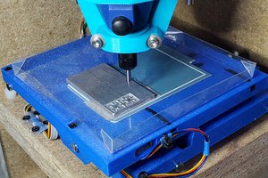
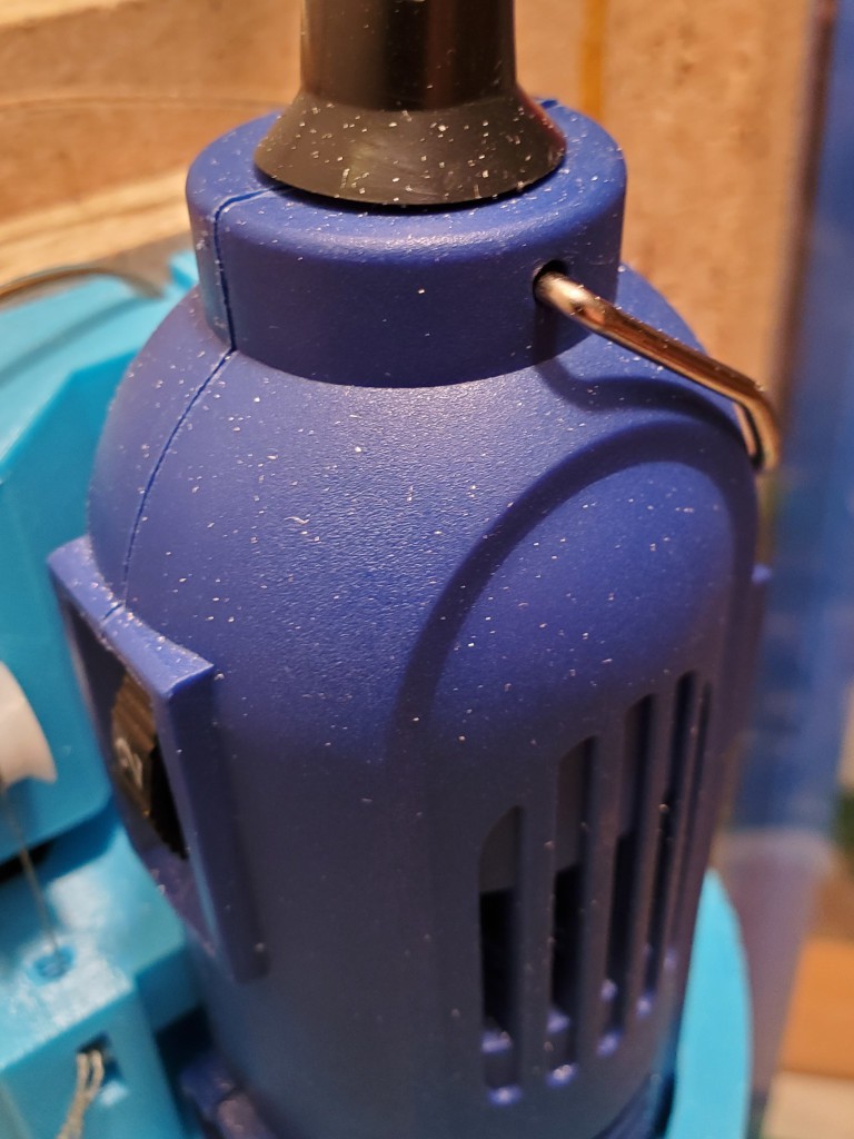
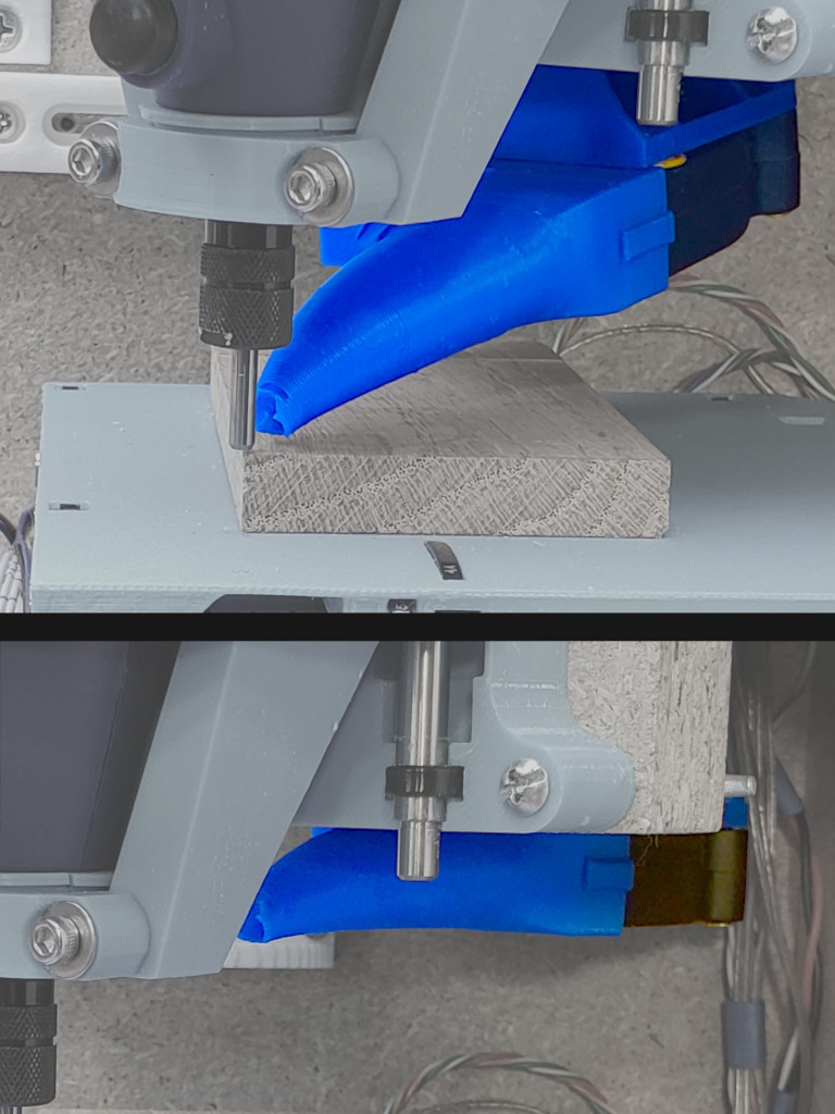
For the spindle, my machine uses a 5010 brushless DC motor turning a 5mm rod that goes down into a wood block with a big 16x35x11mm bearing at the bottom, which fits around an ER11 extension chuck. Having the bearing so close to the bit gives excellent rigidity. It does cover up the wrench flats in the chuck, but instead of using two wrenches you can just grab the rotor of the motor while you tighten the ER11 nut with a wrench.

But the 5010 motor needs an ESC, and a servo tester to tell it what speed to go, and some kind of power supply to provide appropriate DC voltage for it, so that may increase the machine size beyond what you save with the smaller motor. Also the big bearing on mine gets hot and I'm not sure why. It really should be an angular contact bearing, but unfortunately there are none available with 16mm ID. I'd like to use a C10 ER11 chuck (10mm integral shaft rather than an extension chuck) with an 7000AC (10x26x8mm) angular contact bearing, but then the motor can't turn it directly like the 5mm shaft. 

Regarding overall machine design, one thing you might consider is making it usable as a little drill press. Very handy to have around if you don't have space for a big one. Try to make it so you can at least get a 2x4 through with enough side-to-side room that you can drill a hole anywhere in it. And put a manual crank on at least the Z axis. But manual cranks on all 3 axes are wonderful to have, even just for positioning after you get the workpiece clamped down. Also nice being able to do simple milling operations without having to mess around with the computer.

  Are you sure? yes | no

Paul McClay wrote 08/31/2020 at 01:42 point

Hi. Thanks for your interest and for sharing your experience and ideas.

I haven't given much attention to the spindle question yet, but appreciate your data points.

Room to pass a 2x4 and manual control sound like great ideas. At first think, I don't know how to add manual cranks without reducing travel distance of the lead screws. Unless maybe... Hmmm...

Start a project to describe your machine?

  Are you sure? yes | no

dekutree64 wrote 08/31/2020 at 03:08 point

Indeed I should :) I'll see if I can get some photos together tomorrow.

  Are you sure? yes | no

dekutree64 wrote 09/02/2020 at 00:20 point

  Are you sure? yes | no

Similar Projects

Does this project spark your interest?

Become a member to follow this project and never miss any updates