 Timo
TimoThe Raspberry Pi can't guarantee the timing on its GPIO pins due to multi-tasking.
So I need to assure a maximum on-time of the inkjet cartridge nozzles in hardware.
I'm using a 555 in monostable mode for this task: SA555P from TI
http://datasheet.octopart.com/SA555P-Texas-Instruments-datasheet-7285002.pdf
One obstacle is the fact that a TRIG signal overrides a THRESH signal.
Which means I need to shorten the pulse in order to shorten the pulse ...
But there's hope: Using an RC-filter at the GPIO roughly shortens the pulse, for fine-tuning and sharp edge is the 555 responsible.
Circuit diagram (calculations below):
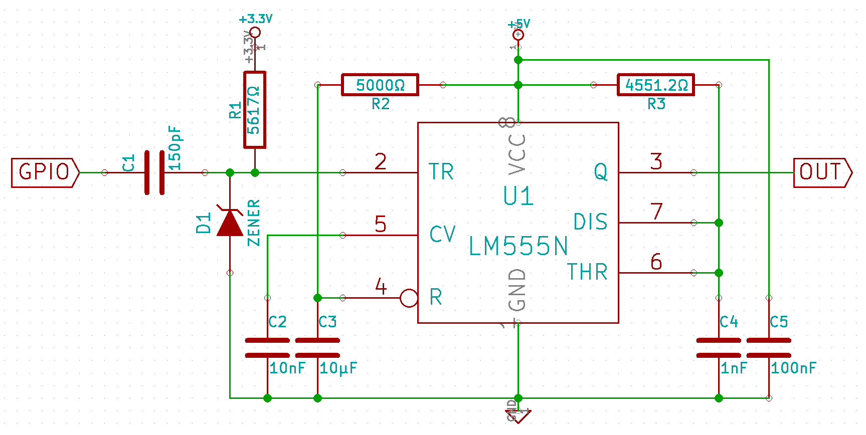
RC-trigger part (C1, R1, D1):
D1 is a Zener diode of 3.6V protecting against overvoltage. The datasheet tells, that the trigger pin of the 555 gives max. 2µA at 0V. In order to trigger the 555 the voltage needs to stay below 1.1V, so let's say: The capacitor C1 must take at least 300ns (some time off the datasheet) to reach the level of 1V through resistor R1. To deal with 2µA, let's see that the maximal flow is much bigger than 2µA (= ignore this amount).
Starting with some ballpark values:
1mA maximal flow gives
1mA => 3.3V / 1mA = 3300Ω =: R1
Give it 300ns to rise up to 1V (buffer of 0.1V included):
Uc = Umax * (1 - e^(-t / (R * C)))
1V = 3.3V * (1 - e^(-300ns / (R1 * C1)))
<=> e^(-300ns / (R1 * C1)) = 1 - 1V / 3.3V
<=> -300ns / (R1 * C1) = ln(1 - 1V / 3.3V)
<=> C1 = -300ns / (R1 * ln(1 - 1V / 3.3V))
So R1 = 3300Ω => C1 = 251.82pF
I got an R1 with 5617Ω which sets C1 = 147.94pF.
My C1 got a measured capacity of 180pF.
Capacitor C2 is just for stabilization. Most circuits I've seen used 10nF, I had 22nF lying around.
Reset time: R2 + C3
This gives some time till the chip has functionality, so it doesn't start with a peak at OUT.
Again doing some ballpark calculations: Say 10µs as a start and charging with 1mA, so worst case RESET current is dealt with. The voltage level must be held below 0.3V in that time.
Uc = Umax * (1 - e^(-t / (R * C)))
0.3V = 5V * (1 - e^(-10µs / (R * C)))
<=> 0.06 = 1 - e^(-10µs / (R * C))
<=> e^(-10µs / (R * C)) = 0.94
<=> -10µs / (R * C) = ln(0.94)
<=> R * C = -10µs / ln(0.94) = 0.0001616151s
C := 10nF => R = 16161.510712Ω
C := 100nF => R = 1616.1510712Ω
Maximal flow:
5V = R * 1mA => R = 5kΩ
=> C = -t / ln(0.94) / 5kΩ
C = t * 0.0032323 / Ω
309.377µs per µF, thus using some µF capacitor.
Result: Using R2 around 5.5kΩ and C1 with 22µF, but the exact values doesn't matter that much, just deactivating the chip for a few ms.
Set the 555 pulsetime through R3 and C4:
pulsetime = ln(3) * R3 * C4
(Most circuit calculators use 1.1 instead of ln(3), because ln(3) = 1.09861228867.)
I want a pulsetime of 5µs, so:
5µs = ln(3) * R3 * C4
Take a look at some test values:
C4 := 10nF => R3 = 5µs / ln(3) / 10nF = 455.1196Ω
5V = 455.1196Ω * I => I = 0.01098612A (while discharging)
11mA is a bit too much for standby in my opinion.
Since things are linear in this formula, let's divide it by 10.
New try
C4 := 1nF => R3 = 5µs / ln(3) / 1nF = 4551.196Ω
5V = 4551.196Ω * I => I = 0.001098612A (while discharging)
1.1mA is better and fine, because it is lower than the typical current consumption of the chip itself (3mA).
I got R3 with 4570.4Ω and C4 with 1nF.

Discussions
Become a Hackaday.io Member
Create an account to leave a comment. Already have an account? Log In.