 Timo
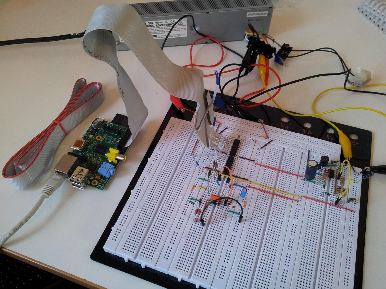
TimoI connected the RasPi with an old floppy IDE cable (cut at one end). It has 8 more pins than the Raspberry Pi, so these are ignored (would be cable ids 27-34).
Here is the mapping of RasPi pins to floppy cable ids (only the first 26 of 34 can have a connection):
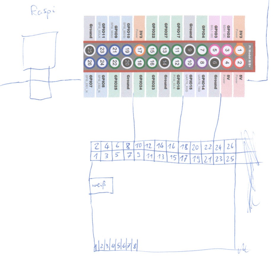
Mapping as seen from the cable (7 pins have a cable connection, but aren't used on the board (the black ones)):
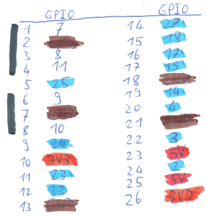
Color coding:
Black: Not connected
Brown: Ground
Red: 5V
Orange: 3.3V
Blue: Used GPIO Pins
The two 5V pins are connected to the breadboards 5V lane, so it is powered through the board. The two 3.3V lanes are used in the 555 timer circuit from one project log ago. Three ground lanes are connected to the ground of the breadboard and two ground lanes aren't connected.
GPIO25 (cable no. 5 between the black blocks) is used for triggering the 555. All other eleven GPIOs are connected to one port of an ULN2803A chip (the long chips in the top) each.
For connectivity I'm using the LAN cable seen in the picture, later I will add a WiFi or Bluetooth dongle.
Discussions
Become a Hackaday.io Member
Create an account to leave a comment. Already have an account? Log In.