I've done plenty of testing and thinking about the power supply, and now that I have an oscilloscope, I can finally verify the performance of my supply. Spoiler alert: it doesn't look good...
Testing:
First, load testing: Here is the power supply outputting 12v at 1.2A through a 10R resistor:
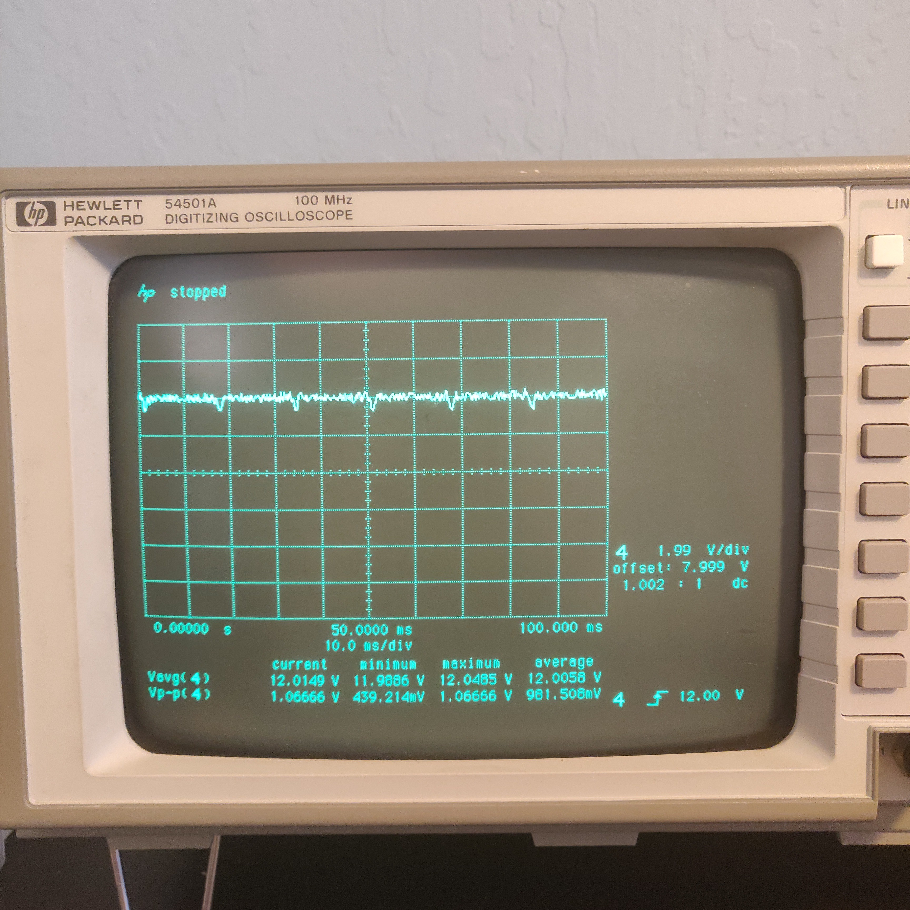
Yea, that's 1v pk-pk ripple, not so good. Although I only specified a maximum voltage of 12v, it can actually go up to about 14. At this point, it looks even worse. The top waveform is the rectified and filtered mains voltage, and the bottom waveform is the output voltage into the same 10R resistor:
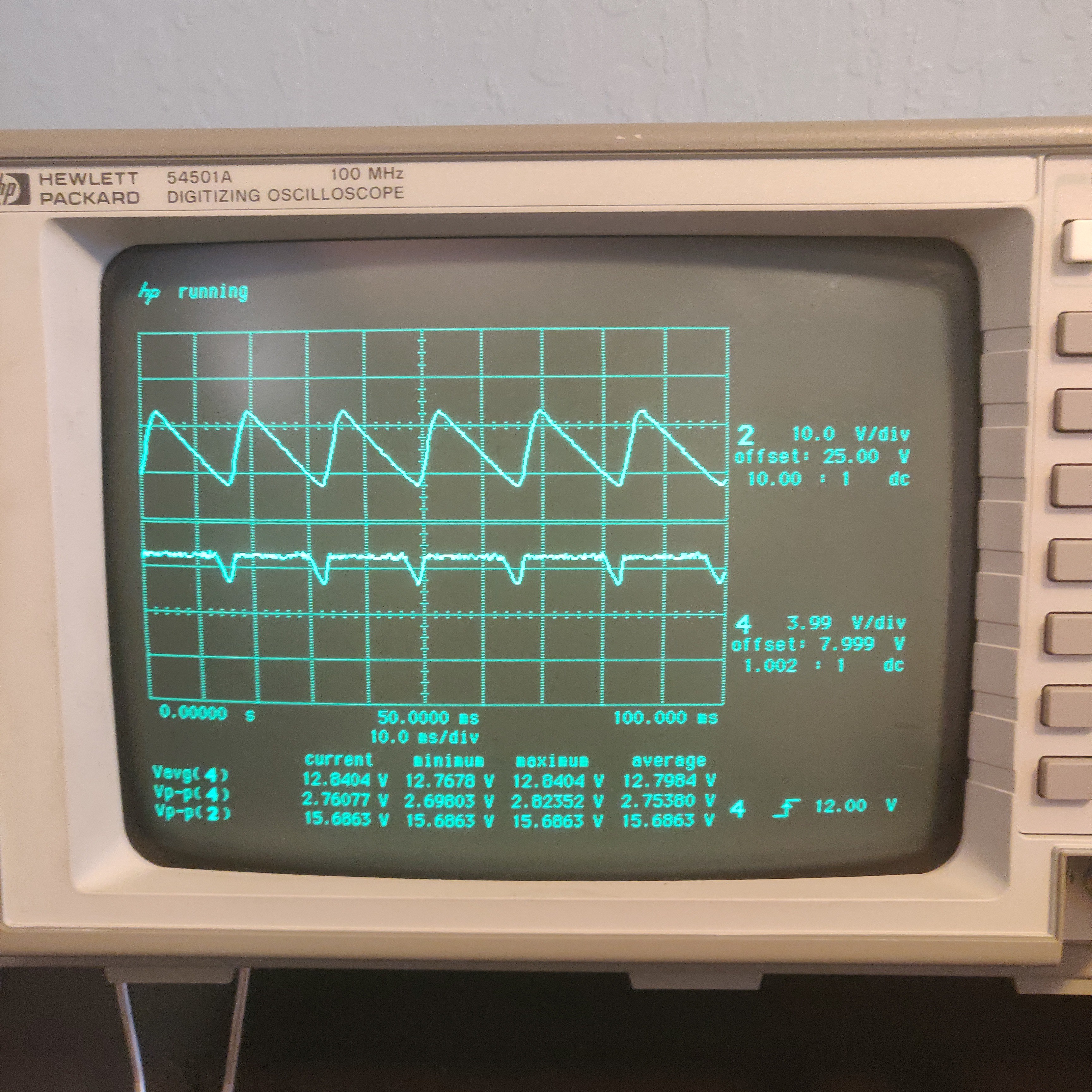
Note for next version: way more capacitance.
Here is the current limiting in action. The waveform on top is the base of the current limiting transistor in the feedback loop, and the waveform on bottom is the output voltage:
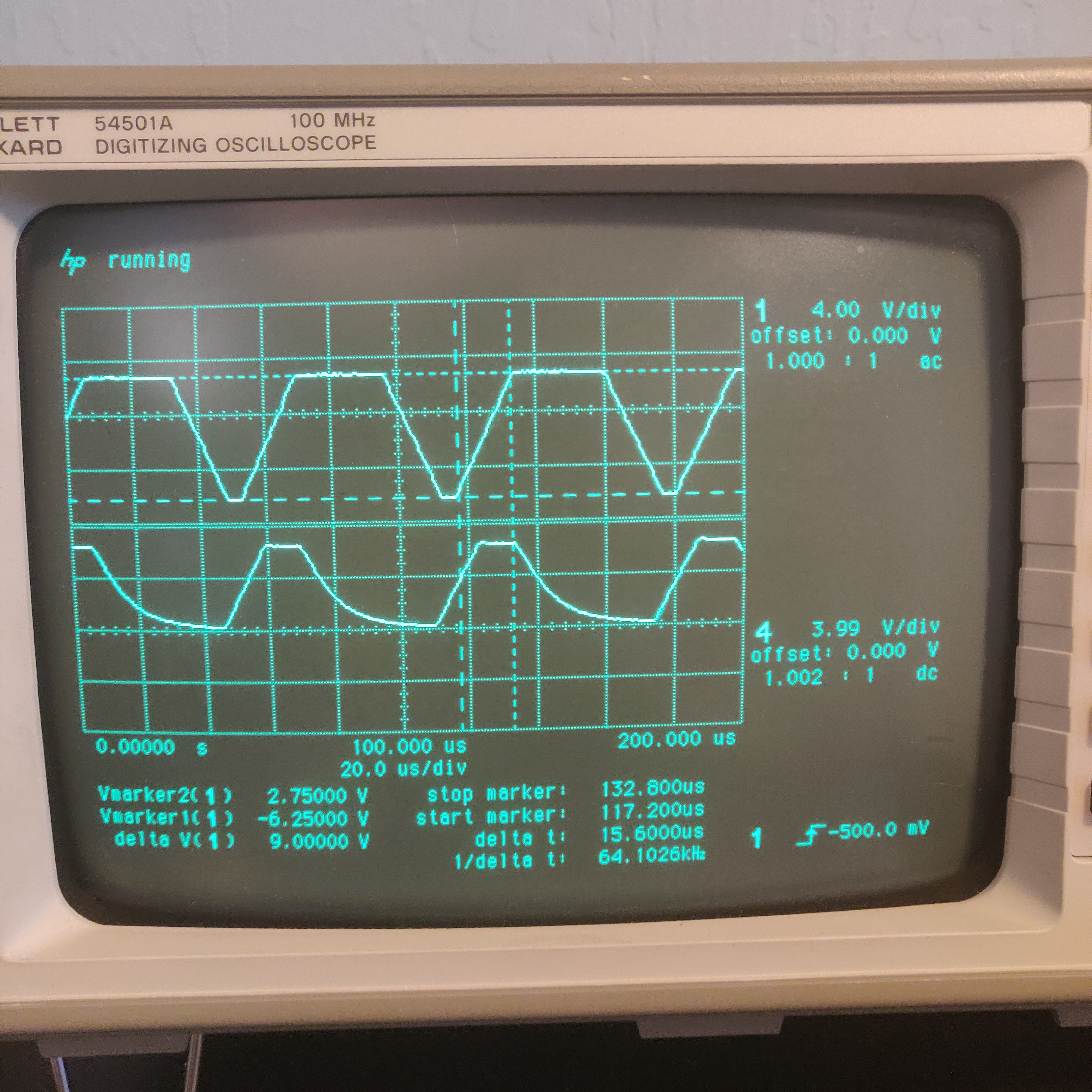
Yea, that's not so good. There appears to be some oscillation. I believe that a low pass filter in the feedback loop would mitigate this, but I'm pretty sure I'm also running into the slew rate of the LM324. It is specified at 0.5V/uS, and the rise time on the top waveform is about equal to that.
improvements:
I don't believe this architecture will carry me very far. In simulating, I could never get the performance I wanted with the transistor current limiting. Additionally, using an integrated linear regulator is too much of a hassle, as it requires negative voltages to reach 0-1.25v. I believe moving to a discrete design would work better. I've already started work on a new and improved design that is digitally controlled. Removing the need for negative voltages is also necessary for this digital control, as I want the digital section to be isolated. Good luck finding a dual secondary winding 36v transformer with center tap!
Discussions
Become a Hackaday.io Member
Create an account to leave a comment. Already have an account? Log In.