Close
0%
0%

Isolated +-50 A current sensor

Very simple +-50 A isolated current sensor with 1.5 MHz bandwidth based on Anisotropic Magneto Resistive sensor technology (MCA1101-50-3).

Similar projects worth following
Very simple +-50 A isolated current sensor with 1.5 MHz bandwidth based on Anisotropic Magneto Resistive sensor technology (MCA1101-50-3). Basically recommended datasheet connection with additional linear 3V3 power supply, varistors for ESD protection and capacitors for increased EMC immunity against external disturbances like bulk current injection (BCI) etc which occurs very often in environment where this sensor is needed (motor control).
Target is to maintain very high isolation voltage, reduce magnetic cross-talk and make it 3 channel unit. Also it needs to fit on single sided PCB milled on my CNC3018.


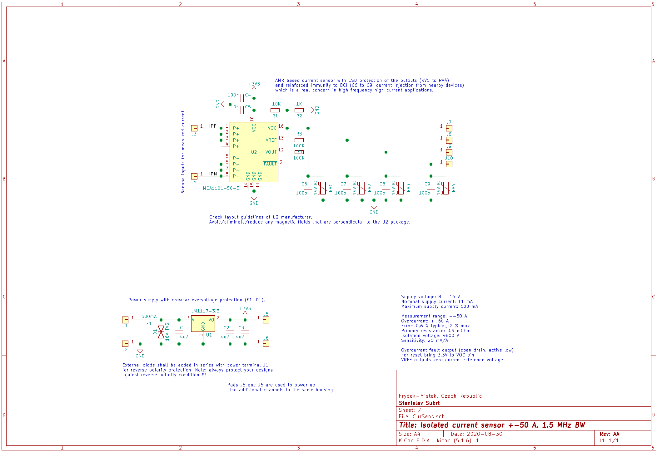
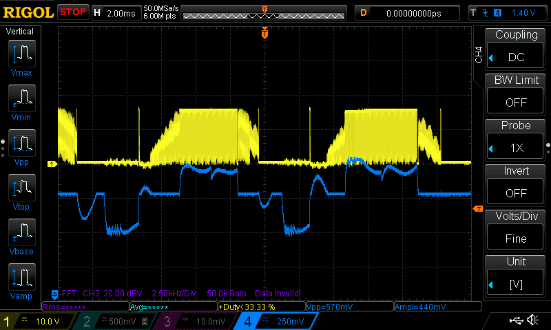
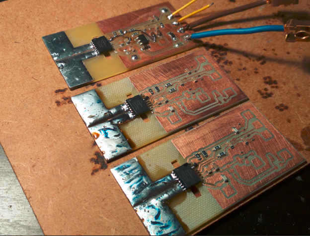
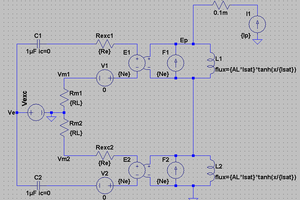
Eventhough the schematic is very straightforward the real challenge in design like this is to overcome various error and noise sources. This kind of sensors is very sensitive to external magnetic fields that are entering IC package perpendicular to its package top plane. Such a field will cause huge offset error or even saturate the output. In static condition (like when magnet is nearby) this offset could be compensated, but typically this issue will occur under high load due to dynamic magnetic fields on the PCB caused either by magnetics (inductors, transformers) or nearby high currents. For real life examples check the build log below - Real life issues.
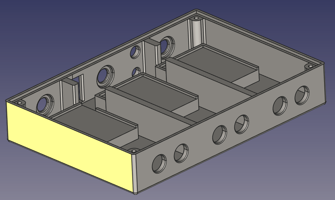
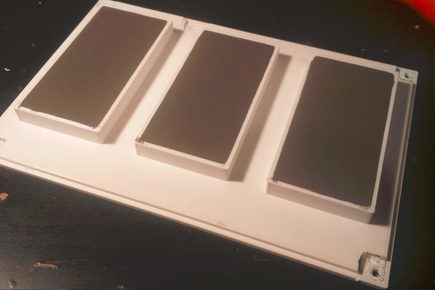
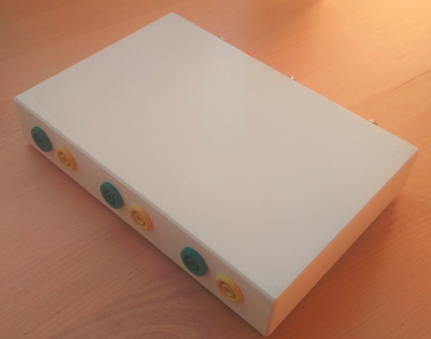
Housing


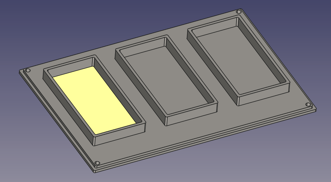
And cover with fences to pour concrete into for more solid feeling.

RevAA ME package.7z

FreeCAD project files and STL models ready for 3D printing.

7-Zip - 5.86 MB - 09/22/2020 at 05:02

Download

RevAA HW package.7z

KiCad project, schematic, layout, gerbers, CAM files for milling.

7-Zip - 3.22 MB - 08/30/2020 at 16:15

Download

  • Works well - it is my daily tool now

    kevarek01/11/2021 at 21:41 0 comments

    Just a quick update - more like closure of this project.

    It works really well, it is mandatory tool for any motor control or power supply designer on budget. Im using it daily now.

    Small example from BLDC control - phase voltage (yellow) and phase current (blue, 25mV/A = 10A/div)


  • Making a three channel unit assembly

    kevarek09/22/2020 at 04:52 0 comments

    Three PCBs were milled and assembled

    Housing has been designed with special care to provide 4 kV RMS isolation barrier.


    Im always pouring some concrete to bottom part of housings because it has much nice feel when using it.

    And finalized unit below (ok I admit it is missing some labels :)

  • Real life issues (not this project)

    kevarek09/22/2020 at 04:48 0 comments

    Here are few issues which you may experience when using AMR current sensors. The biggest challenge is that they seem to be so perfect in static conditions but when under heavy load many errors may add to real signal which typically leads to complete malfunction or worse sporadic malfunction/destruction of the whole device. See below my experience from another project.

    Signal Id offset error(Id current - grey - signal shifted in amplitudes)


    Id current saturation error


    Id current seemingly OK after a small piece of soft magnetic steel has been placed on top of the integrated circuit. But check the -2 A offset error when no current is which is caused by the residual magnetization of this new shield.


  • Functional and bandwidth testing

    kevarek08/30/2020 at 16:51 0 comments

    Yellow: voltage across 2.2 Ohm resistor, maximum is 22V (current = voltage / resistance in any given time)
    Blue: current sensor output voltage.

    Switched mode power supply with 22V on the output was shorted via 2R2 resistor. Current rises to 5 A immediately but after that the power supply load response takes 2us to regulate it to desired voltage and hence 10 A current. Sensor output lags approximately for 200 ns and rises with maximum slope 10 A/us untill it catches up with the output. This data is not ideal for bandwidth measurement but it confirms the functionality of the sensor. Also for sure there is no need to not believe to the IC datasheet.

View all 4 project logs

Enjoy this project?

Share

Discussions

Similar Projects

Does this project spark your interest?

Become a member to follow this project and never miss any updates