Do you like shooting games? I'm sure that in addition to playing on the computer, you already had the desire to play in real life. Playing a game with so much action gives us adrenaline and is fun when playing with a group of people.
But I guarantee one thing for you: Shooting games are possible thanks to paintball and airsoft. There are 2 games in which we can assemble teams of people and each person will have a weapon. This gun has paintballs or paintballs (airsoft).
With them, players will be able to attack and defeat the enemy team through shots or when a terrorist bomb is detonated.
These are some game modes. In addition to these two, we have the modality of conquering territory. Teams struggle to dominate territory and the one that dominates more territories over time will win the game.
From these modalities, we will develop a fake bomb with the functionality of conquering territory and, also, of explosion based on a pre-programmed time.
The figure below shows the structure of the fake bomb with Arduino.
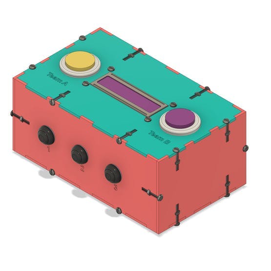
Figure 1 - Arduino fake bomb for Airsoft and Paintball.
Below we will explain the complete structure of this pump. We will talk in detail about its operation and structure.
This project was developed with support and partnership from the company JLCPCB PCB Factory. The company JLCPCB offers discount and PCBs for $2.
Now, we'll explain our project of a fake bomb with Arduino to conquest the war in airsoft or paintball.
How to develop an Arduino fake bomb for Airsoft and Paintball
The fake bomb has a total of 5 buttons. We have 3 buttons to configure the operating mode and other parameters. These buttons are represented by buttons 1, 2, and 3, as shown below.

Figure 2 -
In addition to these buttons, we have the 2 buttons yellow and purple. These two buttons are used for the territory conquest mode. This modality will be discussed in this article.

Figure 3 -
The territory conquest modality has several devices scattered around the map and teams need to conquer and defend these territories.
The winning team is the one that occupied the largest number of territories in a given time programmed by the game judge.
For this modality, we use yellow and purple buttons.
Team A, for example, must press the yellow button for a programmed time. When that time passes, the territory is dominated.
This same process goes for the purple button of team B.
But make no mistake. This is not an easy task. In addition to conquering, they need to defend the territory.
That's when the adrenaline in Airsoft or Paintball starts. You need to fight and defend to dominate each territory in the game.
Next, we will present the circuit structure for this project.
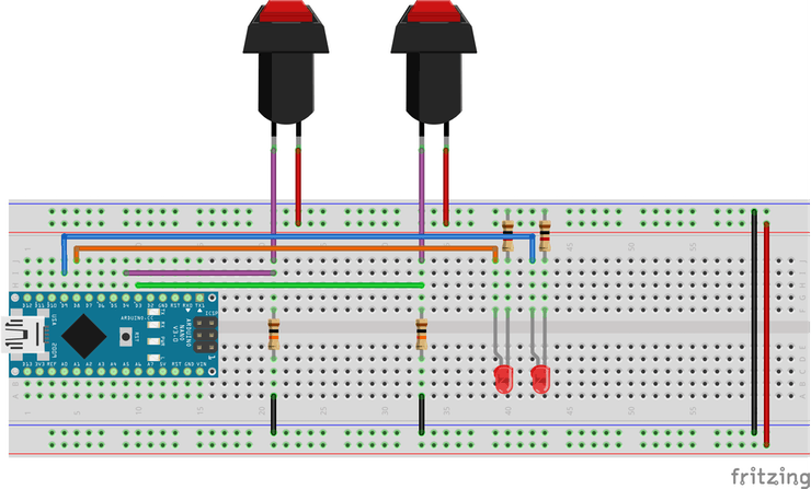
Figure 4 - Electronic Schmatic of the Circuit.
As you can see, we have the circuit structure with two buttons and two signaling LEDs, which are connected to an Arduino Nano.
In the case design, the LEDs are already embedded in the button structure itself. In addition, we will use an Arduino UNO in the internal control of the enclosure.
Next, we will present the programming logic for this project.
Development of programming logic for the territory conquest mode
The logic is simple and is based on the logic of the Arduino millis function. The following is the complete logic for the game mode shown above.
bool TeamA = 0, TeamB = 0;
unsigned long int tempo_atual = 0;
unsigned long ultimo_tempo = 0;
void setup()
{   pinMode(3, INPUT);   pinMode(4, INPUT);     pinMode(8, OUTPUT);   pinMode(9, OUTPUT);     digitalWrite(8, LOW);   digitalWrite(9, LOW);
}

void loop()
{   TeamA = digitalRead(3);   TeamB = digitalRead(4);     if(TeamA == 0 && TeamB == 0)   {    tempo_atual = millis();    ultimo_tempo = tempo_atual;   }     if(TeamA == 1 && TeamB == 0)   {     tempo_atual = millis();          if((TeamA == 1) && (tempo_atual - ultimo_tempo >= 10000))     {       digitalWrite(9, LOW);       digitalWrite(8, HIGH);              ultimo_tempo = tempo_atual;     }     }     if(TeamA == 0 && TeamB == 1)   {         tempo_atual = millis();          if((TeamB == 1) && (tempo_atual - ultimo_tempo >= 10000))     {       digitalWrite(8, LOW);       digitalWrite(9, HIGH);              ultimo_tempo = tempo_atual;     }   }
}
Initially, variables were declared and the setup function was also declared.
bool TeamA = 0, TeamB = 0;
unsigned long int tempo_atual = 0;
unsigned long ultimo_tempo = 0;
void setup()
{   pinMode(3, INPUT);   pinMode(4, INPUT);     pinMode(8, OUTPUT);   pinMode(9, OUTPUT);     digitalWrite(8, LOW);   digitalWrite(9, LOW);
}
Next, we have the creation of the main logic in the void loop function. This logic was developed to monitor which button was pressed for 10 seconds.
If one of the buttons is pressed for 10s, the team's LED is turned on and the territory becomes the type that managed to conquer the territory.
The logic is presented below.
void loop()
{   TeamA = digitalRead(3);   TeamB = digitalRead(4);     if(TeamA == 0 && TeamB == 0)   {    tempo_atual = millis();    ultimo_tempo = tempo_atual;   }     if(TeamA == 1 && TeamB == 0)   {     tempo_atual = millis();          if((TeamA == 1) && (tempo_atual - ultimo_tempo >= 10000))     {       digitalWrite(9, LOW);       digitalWrite(8, HIGH);              ultimo_tempo = tempo_atual;     }     }     if(TeamA == 0 && TeamB == 1)   {         tempo_atual = millis();          if((TeamB == 1) && (tempo_atual - ultimo_tempo >= 10000))     {       digitalWrite(8, LOW);       digitalWrite(9, HIGH);              ultimo_tempo = tempo_atual;     }   }
}
In the void loop function, we perform the reading of the pressed button. After reading, we check which button was pressed and monitor its time-pressed.
In addition, we have three conditions, as is shown below.
The first condition is presented below.
if(TeamA == 0 && TeamB == 0)
{    tempo_atual = millis();    ultimo_tempo = tempo_atual;
}
This condition checks that the 2 buttons are not pressed. If this is true, it reads the millis value and stores its value in the tempo_atual variable.
This variable will be used as a reference to check if the button press time is longer than 10 seconds.
If the time-pressed is longer than 10 seconds, the team wins the place. The main logic is presented below.
if(TeamA == 1 && TeamB == 0)
{   tempo_atual = millis();        if((TeamA == 1) && (tempo_atual - ultimo_tempo >= 10000))   {     digitalWrite(9, LOW);     digitalWrite(8, HIGH);            ultimo_tempo = tempo_atual;   }  }
The above condition will be true if team A is trying to dominate the territory and team B is not dominating the territory.
If this is true, the execution flow enters the condition and captures the millis time and stores it in the variable actual_time.
Then, it checks if the time the button is pressed (current_time - previous time) is greater than or equal to 3000 (3s).
If this is true, the LED of the enemy team is turned off and the LED of the team is activated to indicate the domain of the territory.
This process is the same for the other button on team B. See the code portion below.
if(TeamA == 0 && TeamB == 1) { tempo_atual = millis(); if((TeamB == 1) && (tempo_atual - ultimo_tempo >= 10000)) { digitalWrite(8, LOW); digitalWrite(9, HIGH); ultimo_tempo = tempo_atual; } }
After that, the code flow goes back to the beginning of the loop and starts all over again.
The complete structure of the Fake Bomb case
Below I present the complete structure of the developed case.

Figure 5 - Structure of the enclosure.
In Figure b and figure c, is possible to see other buttons to power on or power off the fake bomb system. In addition. we have access to USB and power for our Arduino UNO.
If you want the file to laser cut, you can send the email for fcodiegomoreira@gmail.com.
Acknowledgment
We appreciate the support and partnership of the PCB manufacturing company JLCPCB for supporting the development of this project. We also emphasize that you can purchase any project and get your first electronic boards for free.