 dekutree64
I built this machine entirely with hand tools, except for a power drill to turn large step drill bits that I couldn't manage with my hand crank drill (would have used a hand brace drill if I had one), and dremel with router base for the screw head pockets in the 1/2" aluminum bed (if I didn't already have it, I would have made a temporary wood or MDF bed with the screw heads sticking up and then used the mill itself to make the final bed).
All three axes use MGN12 linear rails (about $10 each from Banggood). The Y axis (bed) has four blocks on two 300mm rails. Z axis has four 200mm rails with one block each. X axis is two 250mm rails with one block each. These cheap rails are not very consistent (the blocks on some were way too loose while others were way too tight), but by mixing and matching blocks with rails I was able to get them all pretty good. All rails have a 1" wide, 1/16" thick aluminum strip underneath to provide a hard mounting surface, preventing the rail from indenting the wood and causing alignment problems.
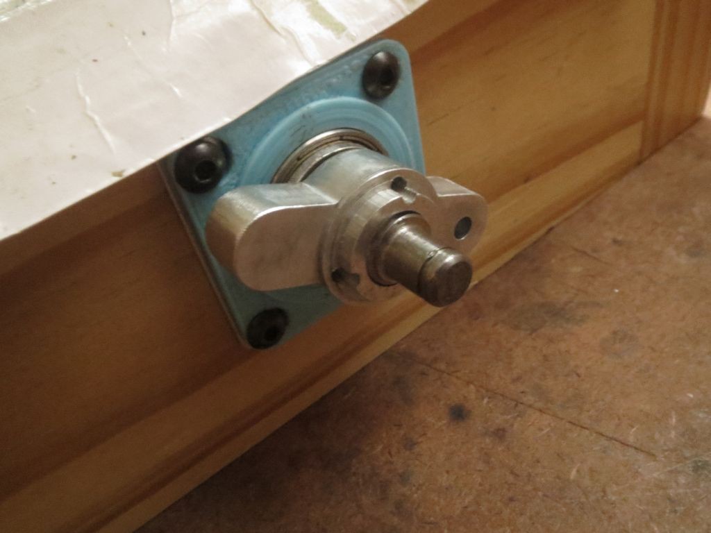
The X and Y axes use SFU1204 ballscrews, mounted using 3D printed cranks and shaft couplers. The way the bearings are placed on the outside surfaces of the frame, the axial forces on the ballscrew are transferred to the bearings via the set screws and 3D printed parts. Not really proper, but it works.
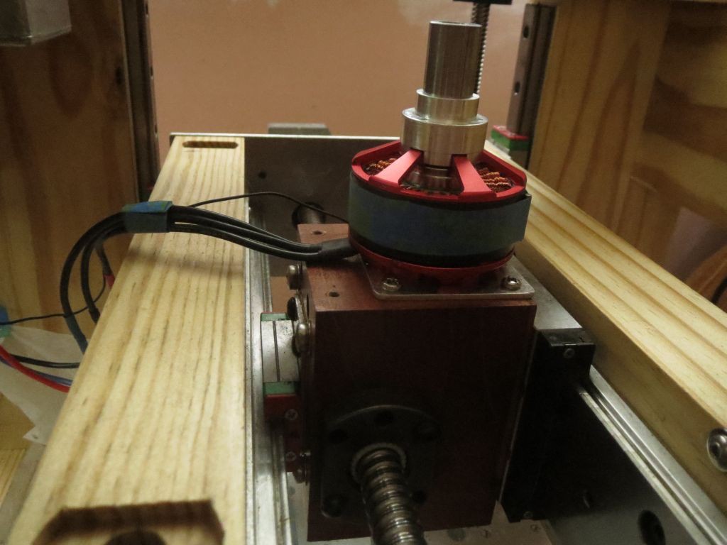
The Z axis uses dual T8 leadscrews, with two nuts each to enable backlash adjustment. The top side nut is buried in a pocket since it would reduce the maximum Z height a bit if it sat on top of the flat surface. The underside nut can be twisted until it's just short of binding, giving very low backlash. I was going to do quad leadscrews, but due to failure of my original plan and subsequent laziness, there are only two now. The others should increase rigidity in the Y direction (prevent tilting of the whole X axis unit), but I'm not sure they're really necessary.
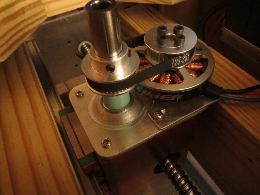
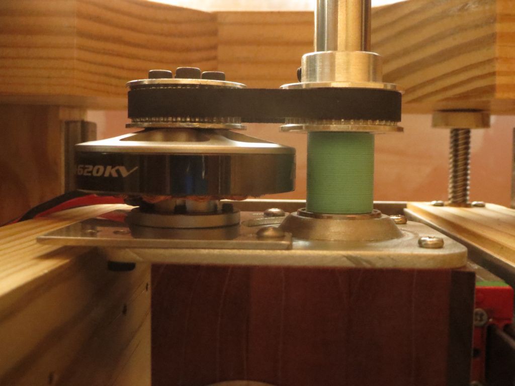
The spindle is a 2 1/4" x 2 1/4" x 3" mahogany block, with a 5010 brushless outrunner on top, a big 16x35x11mm bearing on the bottom, and ballscrew nut going through the side of it. I replaced the motor's shaft with a 5mm rod going down into the block with an ER11 extension chuck on it. Normally you put two bearings on the 5mm rod and then have the chuck dangling on the end of it, but with the big bearing around the chuck itself, rigidity is much improved. It does cover the wrench flats in the chuck, but instead of using two wrenches you can simply grab the motor with your hand and then use a wrench on the chuck nut. Can't get quite as tight, but I haven't had any trouble with bits slipping.
The big bearing gets hot during longer operations, and I'm not sure why. I'm pretty sure everything is aligned well. Ideally I'd like to use a C10 ER11 chuck (integral 10mm shaft rather than the 5mm extension chuck) with 7000AC (10x26x8mm) angular contact bearing, but I don't think there are any small motors that can directly turn a 10mm shaft, and there's no space to move the motor off to the side and turn it with a pulley or gears.
Construction of the frame was fairly difficult, getting everything perfectly square. Tools used: Hand crank drill, dozuki saw, block plane (for rough dimensioning), jointer plane (very sharp, able to take fluffy thin shavings), sandpaper for squaring the endgrain, and an extra-extra-coarse DMT Dia-sharp stone for final flattening of all surfaces. Straightedge, combination square, and $5 digital calipers for measuring. Probably a few other tools here and there. Glued together using hot hide glue (makes strong endgrain joints if you pre-coat with glue to clog the pores, let it dry, re-flatten, and then do the real glue-up), and finished with shellac (give it one heavy coat to raise the grain and harden the surface, then a light sanding or scraping to smooth it out, and another coat to make it shiny).

 Greg Duckworth
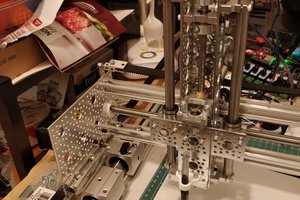
 Ted
Ted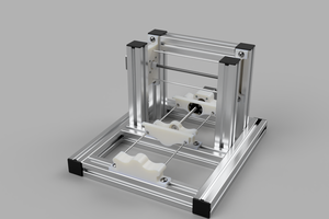
 Myles Eftos
Wow, i love this CNC, it's also so beautiful, it could be in a living room and no-one would object. I love what you did with the spindle - the 5mm shaft is normally what kills the chinesium mini-CNCs for machining aluminium, it's just too wobbly.