Measuring the temperature of a given environment is very important, because, through this parameter, it is possible to control various processes such as industrial ones, those related to incubators, processes for refrigerating small devices or large systems, and also in Central Processing Units (CPU) of computers, among other applications.
In addition to these applications, the appropriately configured temperature sensor can be used to activate other devices, when the ambient temperature is above or below a predetermined value, for example, the air conditioners act more intensely when the temperature of an environment is above the set value, causing more heat to be removed from the environment until it reaches the set temperature.
Thus, a similar application was developed in the case of the Didactic Thermometer using the LM35 temperature sensor, as shown in Figure 1.

Figure 1 - Didactic Thermometer Case Using the LM35 Sensor.
With the development of this Didactic Thermometer case, you will learn both how to assemble the basic circuit using the Arduino as in previous projects, and how to program it.
The Didactic Thermometer implemented has a simple structure, with the LCD display (Liquid Crystal Display), the LM35 temperature sensor, 3 green Led's, 3 yellow Led's, 3 red LEDs and a Buzzer.
The LM35 temperature sensor detects the ambient temperature, and transmits the value to the Arduino, which is responsible for processing the signal, and then activating the corresponding LEDs in the Buzzer according to the temperature range configured in the program.
In this article, you will learn how to program and use the LM35 temperature sensor, as this is an analog temperature sensor with an important precision margin.
Therefore, through this article you will learn:
- Know the structure of the case of the Didactic Thermometer and the Analogic Temperature Sensor LM35;
- Understand how the LM35 Analog Temperature Sensor works well with other devices in the house;
- Perform the Communication between the LM35 Analog Temperature Sensor, the Led's, the Buzzer, the LCD display, and the Arduino UNO
- Couple the structure of the LM35 Analog Temperature Sensor and the other components to the didactic case developed.
- Develop a JLCPCB Printed Circuit Board for this project
Now, we will start the complete presentation of the development of the Didactic Thermometer Using the LM35 Temperature Sensor.
Developing the Thermometer Project
This project consists of presenting a didactic model of a thermometer using the LM35 temperature sensor with the UNO Arduino development board.
The project basically consists of the temperature sensor, responsible for detecting the ambient temperature, and through its housing, converting that temperature into an analog signal.
Led's and the Buzzer will be used as beacons and, finally, we have the LCD display that will show the process temperature value, as shown in Figure 2.
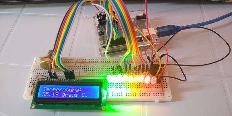
Figure 2 - Circuit proposed for the operation of the Didactic Thermometer.
The LM35 temperature sensor consists of a housing with a shape close to that of a semi-cylinder with three pins.
According to its datasheet, the sensor has a resolution of 10mV / ºC, that is, every 1 degree Celsius, it supplies 10 mV in its output. Equation 1 illustrates the conversion.

Equation 1 - Temperature Conversion on the LM35 Sensor. Source: Texas Instruments.
In this way, the Arduino captures the signal, so that it can be converted in a range from 0 to 1023 (analog value) into a signal from 0V to 5V (voltage signal).
After that, a linear interpolation is made between these values and it is possible to find the voltage value corresponding to the temperature captured by the sensor.
Finally, this value is divided by the resolution and thus the temperature value registered by the sensor is found. Figure 4 illustrates the LM35 temperature sensor.
All communication of the Didactic Thermometer will be done through the LCD display, which will send messages...
Read more »
 davedarko

 NPN
NPN
 Hemal Chevli