 Michael Gardi
Why Another Turing Machine Project?
This started with a comment made by Newspaperman5: "Sweet! I would love a smaller and/or more capable version of [TMD-1] as a desk toy!", and it made me realize that I did too! I loved messing around with TMD-1. The tile interface is fun to use. There is enough there for educational purposes but I found that I am wanting more.
In this next iteration I will try to bring forward the simple to use, easy to understand, principles from TMD-1, but the emphasis will definitely be on increasing the overall functionality.
I'm thinking a 6-state / 6-symbol machine would be a good target. With it for instance, you could explore the 5-state / 2-symbol "busy beaver" problem for which there is still no definitive solution. Pretty cool.
So that's the why, and a little bit of the what, so now I just have to figure out the how.
Keeping the Tile Interface?
IMHO the best part of TMD-1 is the tile interface. Programming the machine by filling out the State Transition Table with "special" tiles feels natural, something about the tactile nature of the process I guess. It's also a lot of fun. I've had a few people run through the Quick Start Guide on my TMD-1 and they all agree: easy and fun. So if at all possible I would like to keep using tiles.
Keeping the tile interface with the larger machine does have some serious issues however, the biggest of which is that the technology that I used to "read" the tiles does not scale well. It took 33 Hall Effect Sensors to interpret the 24 tiles on the State Transition Table for TMD-1. A 4-state / 4-symbol machine would require 88 sensors, and my 6-state / 6-symbol machine would need 252 sensors. At about $2 apiece it adds up pretty quick, not to mention the wiring nightmare. Clearly this will not work. I need a better way.
To keep the State Transition Table layout down to a reasonable size with a 6-state / 6-symbol machine, the tiles themselves will have to be significantly smaller that those on TMD-1, as much as one quarter the size perhaps. I think that this would rule out something like NFC or RFID. The tags would just be too close together and even if they were not, you would have to implement a mechanism to move a reader across each tile. Still need a better way I think.
Newspaperman5: suggested: "My only viable solution would be to place 2 electrodes on each block with a resistor in it, and then reading the resistance, but that makes block-production pretty complicated compared to just placing a magnet or 2 in them, and I’m not sure how reliable it would be". Interesting idea, but I must say that I agree with his comments about block-production and reliability. Also for larger machine you would still have to somehow route 150 inputs into analog pins on the controlling CPU.
About the only thing that I can think of that might work is Optical Character Recognition (OCR). Mount a camera above the State Transition Table matrix, take a picture, and process the resulting image. In a past life I had the opportunity to work with Tesseract. An OCR engine originally developed by Hewlett-Packard as proprietary software in the 1980s, Tesseract was released as open source in 2005 and development has been sponsored by Google since 2006. Having used the software, I am fully aware of its limitations. While it works quite well at deciphering and extracting the text from say the page of a book, a letter, or other similar documents, one often gets poor results when trying to read from a structured layout like say a "State Transition Table". Still I am pretty confident that I can get it to work.
What Technologies?
Having decided to at least try using OCR, and Tesseract specifically, I need to decide what I'm going to run my new machine on. Throw in the requirement that, if all goes well, I will have to take a picture of the State Transition Table of my larger machine to apply the OCR to, and I'm coming up Raspberry Pi. It doesn't hurt that Pis are well understood and supported by the maker community. A quick search for "tesseract and raspberry pi" turns up a lot of relevant howtos on making this work.
Thinking ahead, my new 6-state / 6-symbol Turing machine will need a way to present the Tape. Since the cells can now contain six (maybe seven ;-) different symbols, a mechanical solution is pretty much out of the question (sorry Flip-Bit). So that leaves 7-segment displays or an LCD of some sort. I'm opting for the Official Raspberry Pi 7" Touchscreen LCD. It's been well reviewed, has for sure hassle-free integration with the Pi, and the touchscreen will give me a lot of flexibility when creating a UI.
So my target runtime environment will be a Raspberry Pi, Official 7" Touchscreen LCD, and a Raspberry Pi Camera module. I'm looking forward to really working with the Pi. It's not like I don't have a bunch of them already running OctoPi, OSMC, OpenMediaVault, and MAME. It's just that those are all distributions that are easily installed and setup. Parts are ordered.
Getting back to running Tesseract on the Pi, all of the howtos suggest using the following software stack:
- Python
- opencv
- tesseract-ocr
- libtesseract-dev
- pytesseract
That sounds good to me. I have never done Python development before so that will be fun.
Since all of the above software is cross platform I have decided to at least start development on my Windows machine. I have installed my old friend Eclipse (the Liclipse distribution) with all of the aforementioned software. Ready to kick some OCR ass.
Kicking Some OCR Ass
I spent some time working in my Liclipse environment with Tesseract, opencv, and numpy under Python. I'll spare you the false starts and head scratching and describe what I came up with so far.
I started by creating a test image to work with. This is a slightly tweaked version of the original that had black squares along the right hand edge in addition to the others. You can see where they were. The black squares are "registration" marks that will help me identify where to find the "Tiles". There will be a black square at the lower left hand corner of each tile.
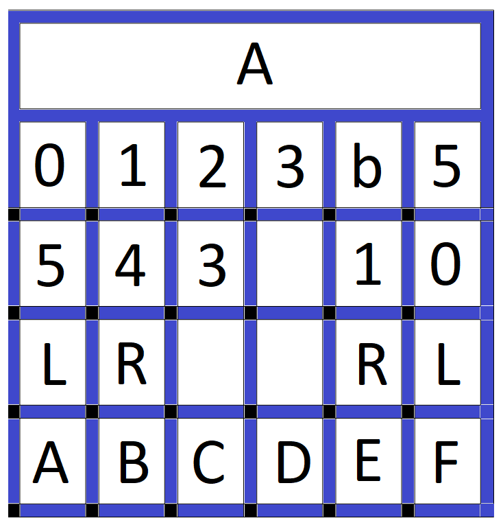
I converted this image to binary, using a fairly aggressive threshold to eliminate all but the white and black pixels. At this point I just care about the registration marks.
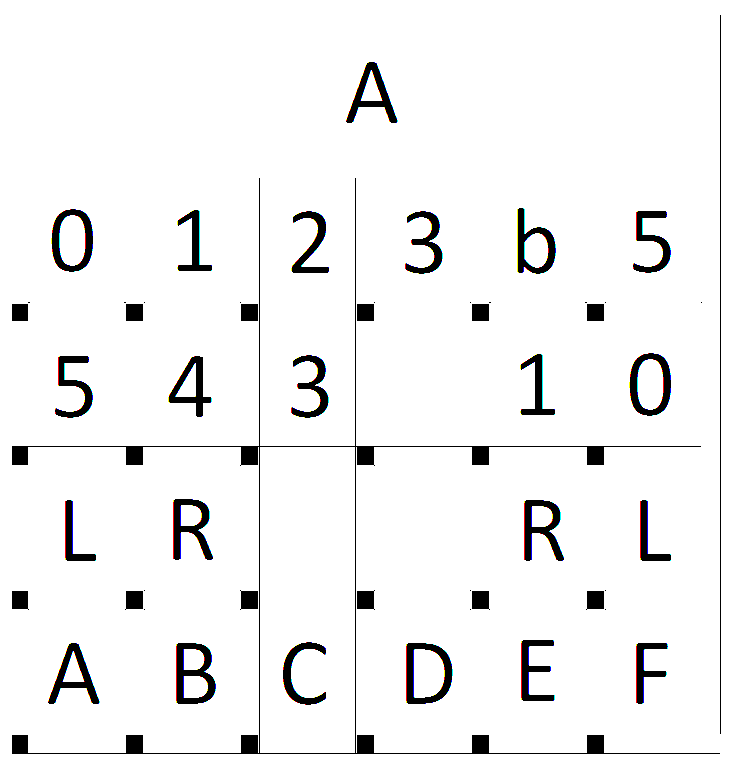
Some noise in the form of the thin black lines was introduced because of the way the the test image was created. At any rate I used a dilate function to eliminate any noise.
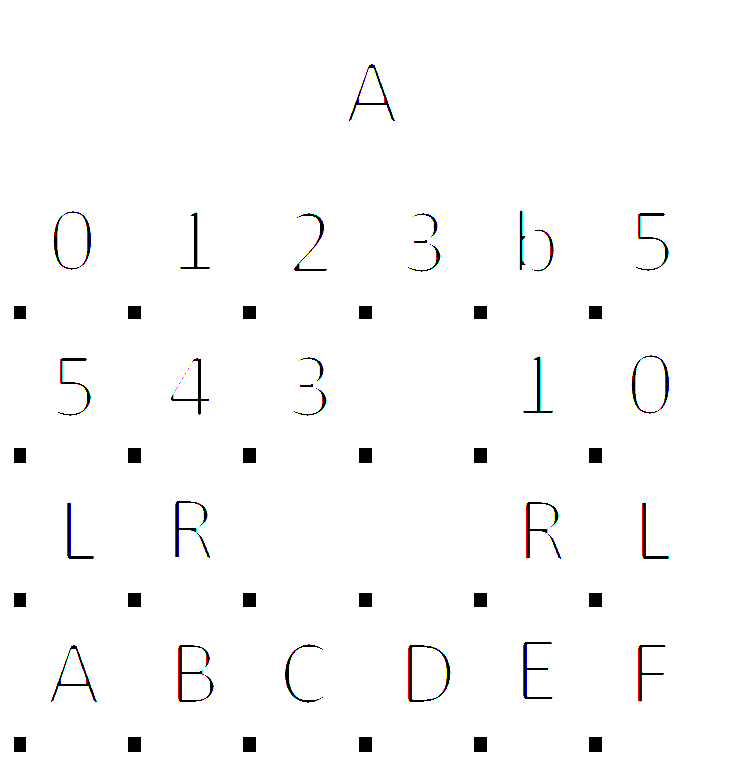
Then I applied edge detection to the dilated image.
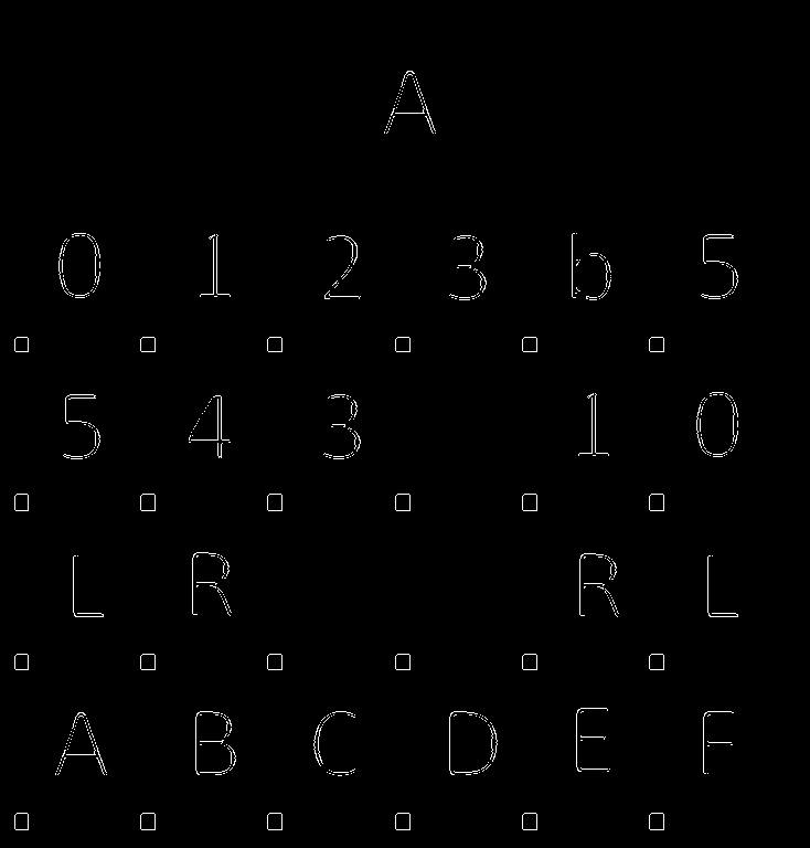
Using a findContours function on these edge lines produces a list of all the "objects" in the image including all the registration marks. I can then check this list to identify just the registration marks. I use the size of each object's bounding box to tentatively identify a registration mark, then verify the selection by ensuring that the pixels in the bounding box are all black. I check my selections of verified registration marks by drawing a box around the tiles that they anchor. These tile bounding boxes are saved to another list.
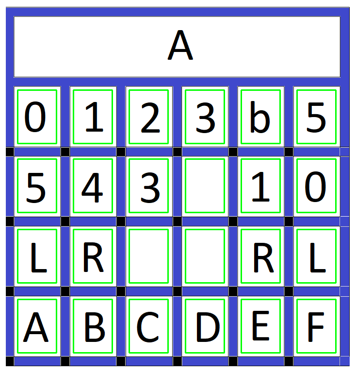
It's Tesseract time. I sort the verified tile bounding box list first by the y position, then the x position. This gives me the tiles in the proper row and column order. Then I pass the sub-image for each tile in sorted order (from the binary image above) to Tesseract. I tell Tesseract that the image passed is a single character plus pass a list of what the valid characters should be (012345bLRABCDEF). Here is the result:
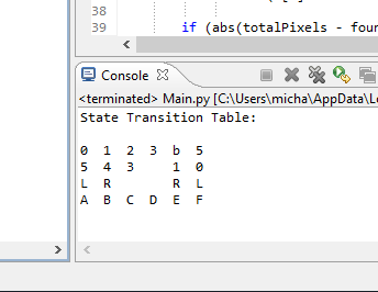
So I was pretty successful. Quite happy. Here is the test code:
import pytesseract
import cv2
import numpy as np
# Get the original image to work on.
image = cv2.imread(r'C:\\Prusa\\TMD-2\\Single State Transition Table Test.png')

# Convert to binary.
ret, binary_image = cv2.threshold(image,10,255,cv2.THRESH_BINARY)
cv2.imwrite(r'C:\\Prusa\\TMD-2\\Binary Image.png',binary_image)

# Dilate to get rid of any noise.
kernel = np.ones((5,5), np.uint8) img_dilated = cv2.dilate(binary_image, kernel, iterations=1) cv2.imwrite(r'C:\\Prusa\\TMD-2\\Dilated Image.png', img_dilated)
# Do edge detection on the remaining what left.
edged = cv2.Canny(img_dilated, 30, 200) cv2.imwrite(r'C:\\Prusa\\TMD-2\\Edged Image.png', edged)

# Find the contours of the edged image objects.
contours, hierarchy = cv2.findContours(edged, cv2.RETR_EXTERNAL, cv2.CHAIN_APPROX_SIMPLE)   # Now we can find all the small squares and use them to determine the # values in the cells of the state transition table.
custom_config = r'-c tessedit_char_whitelist=012345bLRABCDEF --oem 0 --psm 10'
cellList = []
for contour in contours:    (x,y,w,h) = cv2.boundingRect(contour)    if (w >= 13 and w <= 17 and h >= 13 and h <= 17):        # Right size but is it all 'black'?        totalPixels = w * h        foundPixels = 0        for i in range(h):            for j in range(w):                k = binary_image[y+i,x+j]                if (k[0] < 10 and k[1] < 10 and k[2] < 10): foundPixels +=1                    if (abs(totalPixels - foundPixels) < 10):            # All or mostly black. Probably a registration point. Show it on original image.            cv2.rectangle(image, (x+w+10,y-10), (x+w+90,y-120), (0,255,0), 2)                        # Create a list of all the cells where tiles can be found.            cellList.append((x+w+10, y-120, x+w+90, y-10))            # Show where I think all of the cells in the state transition table are.        cv2.imwrite(r'C:\\Prusa\\TMD-2\\Cells Image.png', image)
# Sort the cellList by row then column and extract the tile values.
lasty = 0;
print('State Transition Table:')
for cell in sorted(cellList , key=(lambda k: [k[1], k[0]])):    if (abs(cell[1]-lasty) > 100): lasty=cell[1]; print() # row changed    cell = binary_image[cell[1]:cell[3], cell[0]:cell[2]]    cell_value = (pytesseract.image_to_string(cell, config=custom_config)).strip()    print('{:2s}'.format(cell_value),end =" ")

# Wait for key press before destroying windows.
cv2.waitKey(0); cv2.destroyAllWindows()
At this point I was sure that I was on the right track. I did some additional testing that I posted in a couple of project logs:
With that I had done enough research to convince myself that I will be able to OCR the State Transition Table and reliably determine what tiles have been placed there. As a result I decided to go ahead and build a 6-state / 6-symbol Turing machine. At this point I changed the status from Research to an Ongoing project to reflect this.
TMD-2 Hardware
My Raspberry Pi 4, camera, and 7" display arrived so I though I would get the hardware part of the build sorted. I designed and printed a stand for the Pi 4 and display.
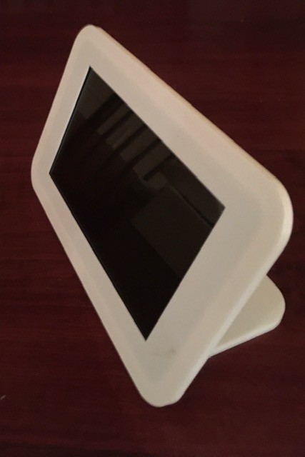
I like the way that the the two components integrate, and don't believe in hiding anything, so it's open concept much like my Working Digital Computer design.
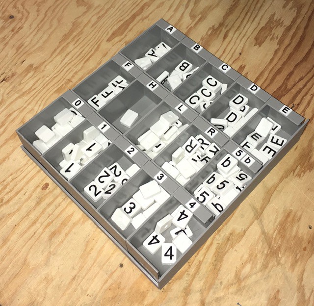
I created 6 "cards" with rectangular indentations for tiles, one for each state (A, B, C, D, E, F).
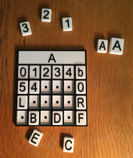
Since I will be combining all six of these I wanted to scale things down as much as possible and still be useable. You can see the A tiles above for comparison, the larger being from TMD-1. The smaller tiles still feel pretty good and are easy to pick and place. Notice that the empty spots above have a square dot as a "place holder".
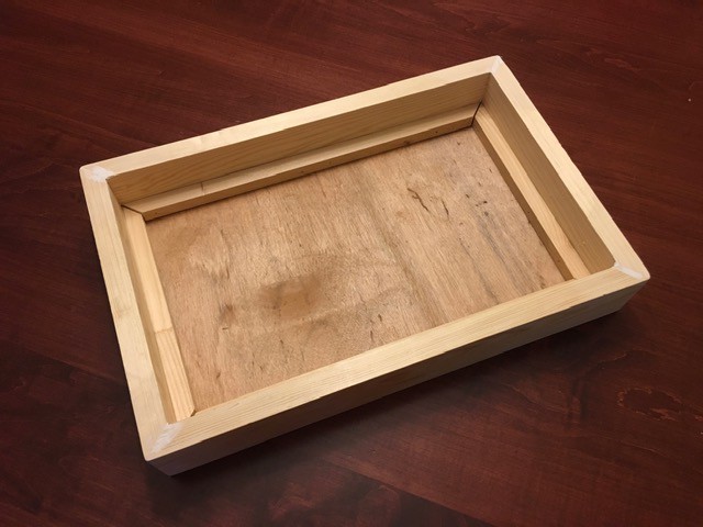
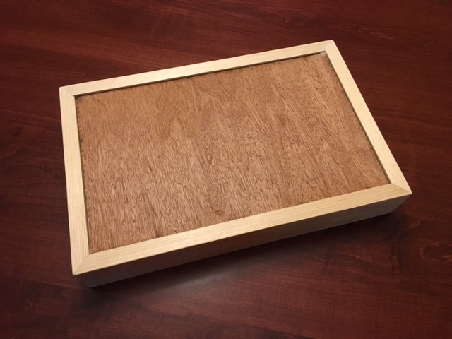
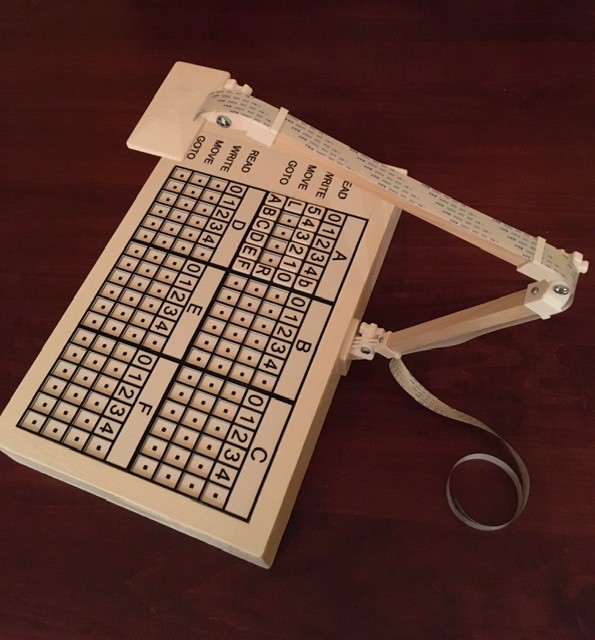
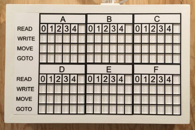
Next I built a base to hold the State "cards" and a legend with labels for each row.
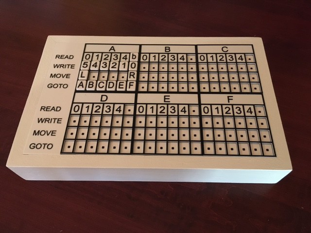
A little white paint plus the addition of the printed State Transition Table pieces looks like this.
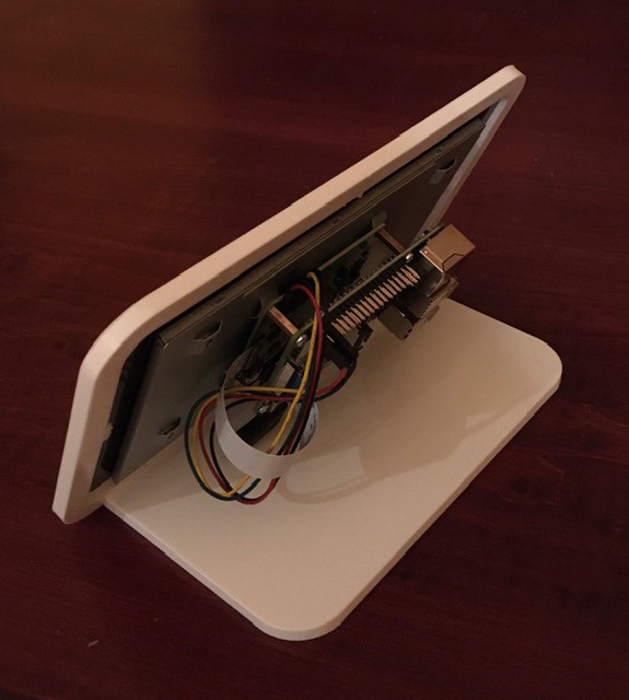
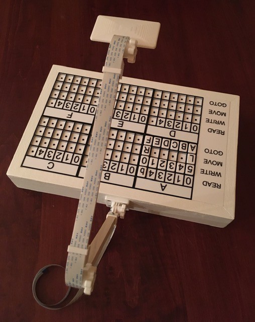
I found an articulated arm design by Chris Rogers (hackoholic) on Thingiverse. His motion capture rig is very similar to the base that I built so it's a good fit. The Raspberry Pi camera snaps snugly into the camera mount and the ribbon cable slides easily through the guides. Great design! Note that since I took these photos I have moved the arm to be centered on just the table (immediately above the B state card.
Finally I put the State Transition Table base camera together with the Pi and display. For development purposes, I have added a wireless keyboard and mouse.
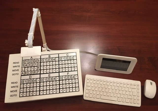
So that's basically the TMD-2 hardware done. It's mostly a software project from here on in.
The TMD-2 User Interface
It took me a while to learning the ins and outs of Python. Having never used it in my professional career (I was mostly a Java guy) I have to say I'm really liking the language. I'm doing all of the UI development on my Windows laptop under Eclipse (because I'm familiar with it) and PyDev. At the recommendation of a fellow makerspace buddy I'm using the PyGame framework. I'm really liking this environment as well. The double buffering makes for very smooth screen transitions. Here is a look at an early version of the UI.
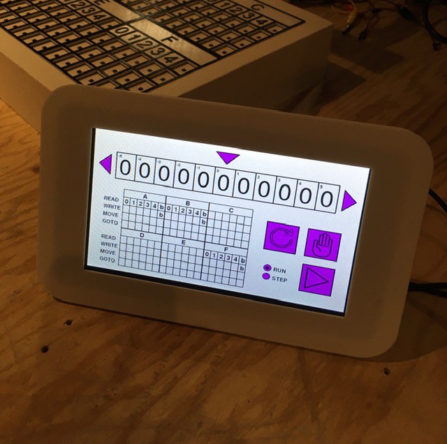
When I copied the python script and images from my laptop to the target environment, a Raspberry Pi with the official 7" LCD touch display, as can be seen in the image above it worked! First try! I have used other pieces of software that claim to be "cross platform", but you end up having to make small (sometimes large) tweaks to get your program working in each new environment. Not this time. I'm very impressed.
TMD-2 The Program?
I continued to work on the TMD-2 user interface while getting the finite state machine running. When I was implementing the state machine, I found myself wanting to enter values into the state transition table to test various features, so I created the ability to add symbols by clicking on the table cells. Each click advances to the next valid symbol for that cell in a circular fashion. Clicking on the top part of the cell will switch to the previous symbol, while a click on the lower part will go to the next symbol. Note that I had already implemented a similar scheme for the tape cells.
As testing continued I got tired of entering the same "programs" over and over so I added the ability to Load and Save "workspaces". A workspace contains a snapshot of the tape and state transition table values at the point that Save is invoked. Save will also produce a dump of the same information plus counts of how many of each symbol were found on the tape. Load of course changes the current console values of the tape and state transition table to those in the saved file.
Here is a quick demo of TMD-2 loading and running a 3-state / 2-symbol busy beaver. The console is running in Demo mode where steps are executed every 300 ms or so:
After the busy beaver program was finished running I saved the workspace to a different file and produced the following summary:
Showing tape from cell -2 to cell 3.
~~~~~~~~~~~~~~~~~~~~~~~~~~~~~~~~~~~~
| 1 | 1 | 1 | 1 | 1 | 1 |

Counts
~~~~~~
0: 0
1: 6
2: 0
3: 0
4: 0
5: 0
b: 0

State Transition Table
~~~~~~~~~~~~~~~~~~~~~~            A
| 0 | 1 | 2 | 3 | 4 | 5 |
| 1 | 1 | - | - | - | - |
| R | L | - | - | - | - |
| B | C | - | - | - | - |
            B
| 0 | 1 | 2 | 3 | 4 | 5 |
| 1 | 1 | - | - | - | - |
| L | R | - | - | - | - |
| A | B | - | - | - | - |
            C
| 0 | 1 | 2 | 3 | 4 | 5 |
| 1 | 1 | - | - | - | - |
| L | L | - | - | - | - |
| B | H | - | - | - | - |
            D
| 0 | 1 | 2 | 3 | 4 | 5 |
| - | - | - | - | - | - |
| - | - | - | - | - | - |
| - | - | - | - | - | - |
            E
| 0 | 1 | 2 | 3 | 4 | 5 |
| - | - | - | - | - | - |
| - | - | - | - | - | - |
| - | - | - | - | - | - |
            F
| 0 | 1 | 2 | 3 | 4 | 5 |
| - | - | - | - | - | - |
| - | - | - | - | - | - |
| - | - | - | - | - | - |
I was able to reproduce most of the runtime features from TMD-1, like highlighting each step within the state transition table while executing the program in Demo and Step modes. I feel that TMD-2 thus maintains the "simple to program and easy to understand' characteristics of it's predecessor.
At some point after adding load and save workspaces, plus the ability to input values directly into the state transition table cells through the console, I realized that I had a pretty good stand alone Turing machine application here. While I personally enjoy the tactile nature of placing physical tiles onto the TMD-1 and 2 transition table panels, clicking on the screen's virtual cells, while not as satisfying, works pretty well. This also makes my "simple to program easy to understand" Turing machine concept available to a much wider audience.
So I took a few days to do some more testing and to figure out how best to package up "TMD-2 The Program". I uploaded my TMD-2 application to a github repository. While it is still intended to be the console for my TMD-2 project with the capability of reading from my tile based state transition diagram panel, I have found it to be a pretty good stand alone application. The repository contains the following:
- Tmd2Console.py - The Turing machine application script.
- TMD-2 Quick Start Guide - In both DOCX and PDF formats, this guide talks a little bit about Turing machines in general, and the TMD-2 implementation specifically. It shows you how to run the TMD-2 application with examples.
- *.png - These are the various image assets required by the application.
- beavern.tmd2 - beaver3, beaver4, and beaver5 are pre-built TMD-2 "programs" for 3-State, 4-State, and 5-State busy beaver implementations. They are referenced in the Quick Start Guide.
A few caveats:
- As this script is designed to be my console application, the screen size is fixed at 800 x 480 pixels, which is the resolution of the 7" display that I am using. As much as possible I have tried to parameterize the placement and size of the screen objects through constants in the script, so it should be relatively easy to make adjustments should you wish to do so.
- I believe that PyGame is the only dependency, but I'm new to the Python environment so I could be wrong about this.
- I have been developing and testing with Python 3.8 and am not sure if other releases will work or not.
- I have done quite a bit of testing, but the code is definitely not "production" ready.
- This is my first Python program. Be kind. I know that underscores (_) are all the rage in Python land, but I'm a CamelCase guy from way back and couldn't quite get the hang of doing it differently.
If you do give this program a try, I would appreciate any feedback, good or bad.
Putting It All Together
I finally got the UI, camera, and OCR pieces of TMD-2 all working together. Here is a short video where I "scan" the State Transition Table tiles with the Pi camera into the UI using Tesseract OCR to determine the symbol in each "cell".
This is running on my Raspberry Pi 4 but I am using RealVNC to capture this video.
One thing you will notice is that the process is not particularly fast. Sigh. I am using the pytesseract library to interface with the underlying OCR engine. I am calling the engine once for each cell because tesseract does not work well with tables. Under the covers, pytesseract "executes" the tesseract engine for each call, essentially using the command line interface. It works well but with significant overhead.
I had hoped to switch to the tesserocr which integrates directly with Tesseract's C++ API using Cython. With it you only invoke tesseract once and use the same instance for making all of your calls. Unfortunately I could not get this to work. Just loading the library in my environment cased a segmentation fault.
So what happened when I clicked on SCAN? First the Pi Camera took the following picture of my state table panel.
Note that this does not represent a Turing program, I just added some tiles to the panel for testing purposes. This image is used as the background for the Scan dialog so that the user can isolate the state table part with the "rubber band" rectangle. Now I could have figured out this bounding box for the table with some clever programming, and I have done this in the past, but the techniques were error prone enough that I ended up using the "rubber bands" as a backup anyway, so I though in this case I would just "cut to the chase" as it were.
When the user clicks START, the bounding box is used to create a "cropped" image that is passed to the OCR code.
Notice that the bounding box doesn't have to be perfect, but the edges in the photo should not be too skewed for good OCR fidelity. The image processing pipeline that was mentioned in previously at this point has changed a little. It starts the same with a conversion from color to greyscale.
Then I do a contrast equalization step.
The equalized image is converted to binary. As has been mentioned, the table borders are removed by applying a single white color "flood fill" to them. I'm amazed at how well this works.
And finally a dilation is applied to the image to reduce noise.
At this point, in my previous trials, I would apply some edge detection and contouring to determine the bounding boxes for each of the tile symbols. Now however, because I know that the bounding box for the table has been well defined, I can just calculate the positions of each cell with reasonable accuracy. Without the borders, there is enough white space around the symbols to provide a good margin of error. So I just go ahead at this point and OCR the cells. As each cell is recognized, the value is passed back to the UI for display.
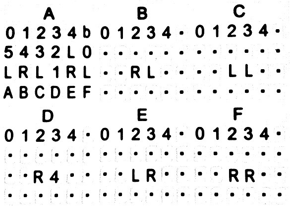
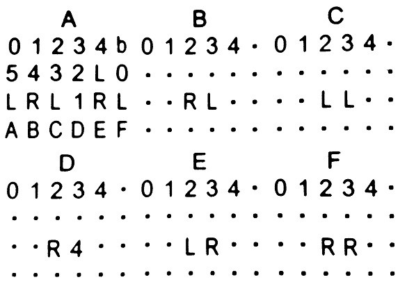
Once all of the cells have been recognized, the state table in the UI looks like this.
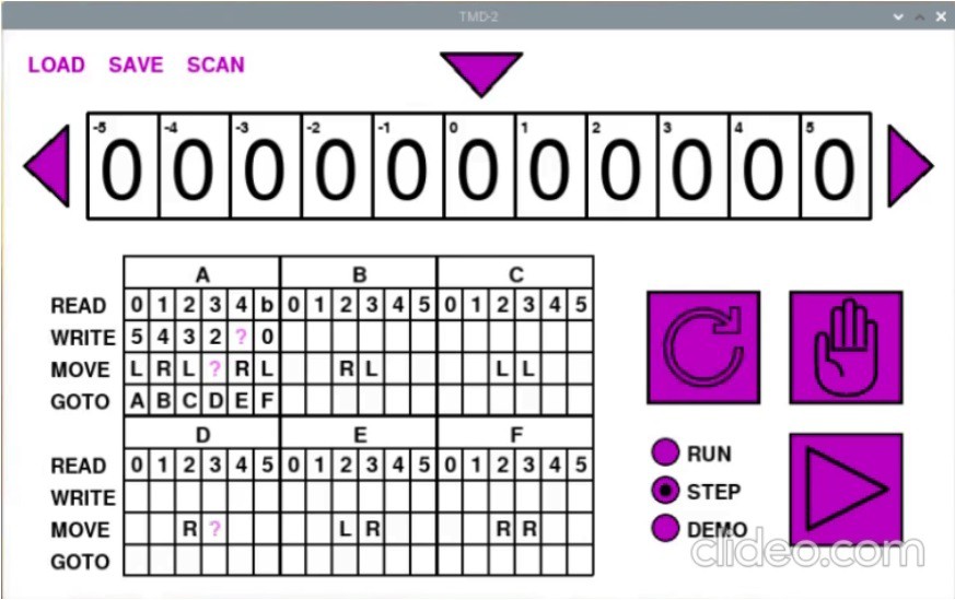
Notice that some of the cells have a purple ?. When loading the cell values, I do a reasonableness check on each. If a symbol does not belong in the cell based on the allowable row values, the ? is shown instead. This is what we see for the L in A-4-WRITE, the 1 in A-3-MOVE, and the 4 in D-3-MOVE. This can happen if the user places a tile in the wrong row, or if the OCR engine fails to identify the a symbol correctly. At this point the user can correct the errors in the UI, or fix the cells on the panel and rescan.
I have updated github with the new and modified files. Note that the Tmd2Console application will still run stand-alone without needing a camera or OCR.
Speeding Up the OCR
I was a little disappointed with how long TMD-2 took to capture the state transition table symbols via OCR. As I had mentioned the pytesseract library "executes" the whole Tesseract engine for each call, essentially using the command line interface, and I was making a call once for each table cell. My planned switch to tesserocr, which integrates directly with Tesseract's C++ API using Cython, didn't pan out due to segmentation fault integration issues.
So I began looking at how I might use Tesseract itself to speed things up. Tesseract has a lot of options. One in particular --psm allows you to define what the image you are passing in represents. Here is the full list of options:
0 = Orientation and script detection (OSD) only.
1 = Automatic page segmentation with OSD.
2 = Automatic page segmentation, but no OSD, or OCR. (not implemented)
3 = Fully automatic page segmentation, but no OSD. (Default)
4 = Assume a single column of text of variable sizes.
5 = Assume a single uniform block of vertically aligned text.
6 = Assume a single uniform block of text.
7 = Treat the image as a single text line.
8 = Treat the image as a single word.
9 = Treat the image as a single word in a circle.
10 = Treat the image as a single character.
11 = Sparse text. Find as much text as possible in no particular order.
12 = Sparse text with OSD.
13 = Raw line. Treat the image as a single text line,     bypassing hacks that are Tesseract-specific.
I had been using option 10 - "Treat the image as single character. ". I started thinking about what it would take to use option 8 - "Treat the image as a single word. ". With "words", I knew it would be important to preserve the spacing between symbols so that they could be written into the correct cells.
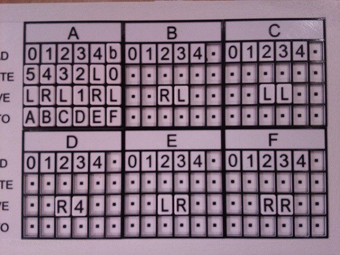
The first thing that I tried was to "read" whole rows from the table across the three state cards. I was hoping that the cells with squares would register as a period (.) or dash (-) or even a space( ), but no such luck. So I took the image of the state table and substituted an M for each empty cell. Here is what a final image that is used for OCR looks like:
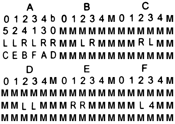
And when I OCR each row (skipping the state headers) as a "word" I get the following results back:
01234b01234M01234M
524130MMMMMMMMMMMM
LLRLRRMMLRMMMMRLMM
CEBFADMMMMMMMMMMMM
01234M01234M01234M
MMMMMMMMMMMMMMMMMM
MMLLMMMRRMMMMML4MM
MMMMMMMMMMMMMMMMMM
I tried using other characters as space substitutes like X and +, but M seems to work the most reliably. I do some reasonableness checks on the retrieved text, like the "word" should be 18 characters in length and should only ever contain characters from the tile set. If this is not the case, I mark the character or row with X's. When retrieving a cell value from the "table" above, if the value is an X, I OCR again for just the character since single character recognition seems to work better than word based OCR.
Here is my new capture process in action:
I have gotten the whole table refresh process down to under 10 seconds. I'm pretty happy with that.
Is TMD-2 a Universal Turing Machine?
Short answer, yes. Turing machines with state-symbol pairs of (4,6), (5, 5), and (6, 4), have all been proven to be "universal". So TMD-2, with 6-states / 6-symbols, certainly qualifies. But what does this mean?
Simply put a universal Turing machine (UTM) is one that can simulate any arbitrary Turing machine on arbitrary input. It achieves this by reading both the description of the machine to be simulated, as well as the input to that machine from its own tape. Another way to put this: the first part of the tape contains an arbitrary Turing machine's state transition table (program) that has been encoded to the tape's input alphabet, and the rest of the tape holds the input to be operated on. The state table of the UTM itself "executes" this program on the tape by shuttling the tape head back and forth between the state table area and the input area, all the while following the rules that have been established for Turing machines like only reading and writing from the head position, and only moving one cell at at time to the left or right.
Since there is no "memory" in a Turing machine (except for the current state register), the process of executing a program on the tape requires that the tape itself be used to remember the current state of the program being executed and the current head position within the input area (at a minimum). This can be accomplished by having two symbols for each tape input, like 1 and say x for a 1 that is also the current position of the tape head, or as in Turing's own example leaving empty spaces on the tape for such markings.
Here are a few links that really helped me understand UTMs. They all come from a post by Mark L Lyons where talks about the book Formal Languages and Their Relation to Automata by Hopcroft and Ullman.
- A Universal Turing Machine - Where Mark corrects a few problems with the UTM presented in the book.
- Implementation Details for Hopcroft & Ullman's Universal Turing Machine - Good example of encoding a state machine as input.
- Correct State Table for Hopcroft & Ullman's Universal Turing Machine - Definition for a 40-state / 12-symbol UTM.
Frankly it hurts my head trying to think about writing a UTM program, especially with only 6-states and 6-symbols to work with, but I accept that it can be done because other people way smarter than me say it is so.
Finishing Touches
To keep things neat I printed a parts box to hold all the tiles.
Since I no longer needed the small black squares in the empty tiles as registration marks, I redid the State Transition Table without them. I think it looks a lot cleaner.
Finally, I created a V1.0 "release" of the console software on github.
Final Thoughts
Designing and building TMD-2 was a great "stretch" experience for me. For the hardware, I had never worked extensively with the Raspberry Pi or Pi Camera. On the software side I had never used Python or PyGame before. So I learned a lot putting TMD-2 together.
Python is a great language but it took a little getting used to. I come from a mostly Java background so giving up on { } as block delimiters felt pretty unnatural. Even after a few months with Python, I still find myself wanting to put a ; at the end of lines. And I never did get the hang of using the _ in variable names, and stuck with camelCase. But that's just me. Python certainly lives up to it's cross-platform name. Development of the console application shifted smoothly between my Windows/Liclipse development environment and my Raspbian target environment. When I started integrating the camera and switched to the Pi for all my development, I found I was easily able to use RealVNC from my laptop to develop on the Pi, which gave me more screen real estate since the only display I had on the Pi was the a 7" touch-screen.
PyGame was recommended to me, and I'm glad that I chose it as the framework for the console. The only thing that I missed was some sort of GUI module. I tried integrating a number of the recommended external libraries, but in the end created my own dialogs in PyGame itself. The disadvantage of doing this is that my implementations were a little feature light, but on the other hand they maintained the aesthetic of the overall application.
There was more software development in this project than I thought there would be. When I first started, I was thinking of TMD-2 as the hardware successor to TMD-1. I would build the hardware and write a little program for the console. Somewhere in the middle writing the console I realized that what I was doing would make a pretty good stand-alone application. I added features so that the program could be run without the camera based input, primarily allowing the state table to be edited with mouse clicks. And since Python is cross platform, it would run almost anywhere. In the end I was thinking of TMD-2 to as a Turing machine program, that took the ease of use and simple to program concepts from TMD-1, and made them accessible to a much wider audience. TMD-2 also supports a cool optional tile based interface for defining the state transition table.
I think with the completion of TMD-2 that I have Turing machines out of my system for a while. On to the next project whatever that might be.
One More Thing
As one last finishing touch I added a virtual keyboard to the TMD-2 application (with thanks to Anthony Maro and William B Phelps for their PyGame virtualKeyboard module).
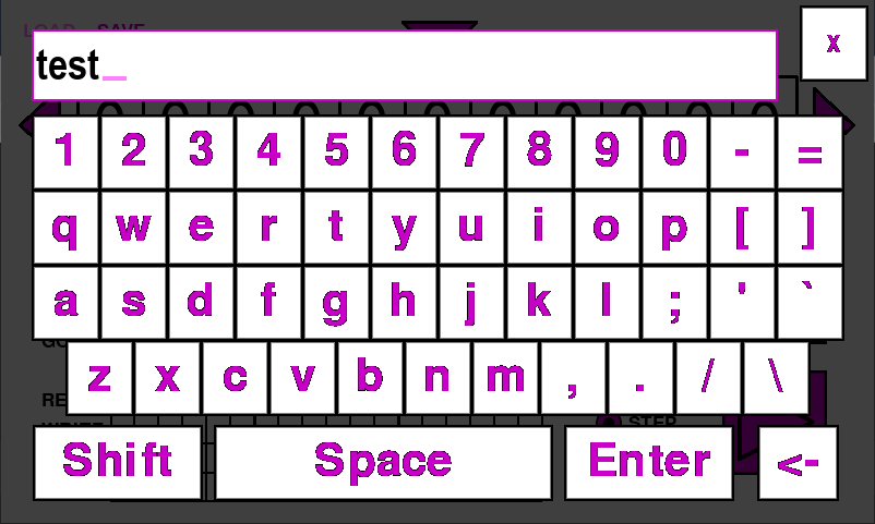
This mitigates the need for a keyboard and mouse if you are using a touch screen like the 7" Raspberry Pi panel that I am using. The github references in this project writeup have been updated to the new release.