 Cees Meijer
A Sonar system consists of several blocks:
- A transmitter stage. Usually a push/pull switching driver consisting of a pair of power FETs and a driver
- A frequency burst generator. An oscillator with gating to create a short burst at the required frequency
- Amplifier and filter for receiving the return signals
- Digitizer to sample the return and make it available in digital form.
For the burst generation and sampling it seems obvious to use a micro-controller board. Preferably one with a decent clock speed so it can support a fast AD converter and a high frequency burst signal with decent precision. As the sound travels through water at 1500 m/s, you will need to sample at at least 150 kHz to get to a centimetre resolution. And I chose a 512kHz piezo, so the controller needs to create a square wave burst at this frequency.
The standard Arduino boards are obviously too slow for this, so I thought of using an ESP32 board like the WEMOS Lolin32. But I soon found out that it is hard to get a good sample rate on the AD inputs. Even when using low level programming it seems that 90 kHz is about the maximum. So I soon came to the Teensy boards. A standard Teensy has an AD sample rate of up to 400kHz. Added benefit: the Teensy platform focusses on audio processing and sampling so a lot of functionality is available out of the box.
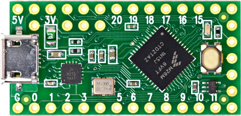 It looks like even the cheapest Teensy, the TeensyLC (yes,LC for Low Cost) might be sufficient for this task. But will it also be able to generate the transmit pulse and necessary control signals ? I will need a 512kHz burst, and some analogue ramp signal for the Time Variable Gain amplifier. And it turns out that this is not just possible, its also very simple.
 int TX_Pin=23;
unsigned long TX_Freq = 512000;
void setup() {
analogWriteFrequency(TX_Pin, TX_Freq);
analogWriteResolution(10); // analogWrite value 0 to 1024
Serial.begin(115200);
}
void loop() {
// Transmit burst
analogWrite(TX_Pin,512);
delayMicroseconds(20) ;
analogWrite(TX_Pin,0);
delay(5);
// TVG Ramp
for (int val=0;val<1024;val++)
{
analogWrite(A12,val); // Use the DAC output on A12
delayMicroseconds(100);
}
}
This simple Arduino code generates a 512 kHz burst, and an analogue ramp signal on the dedicated DAC output:
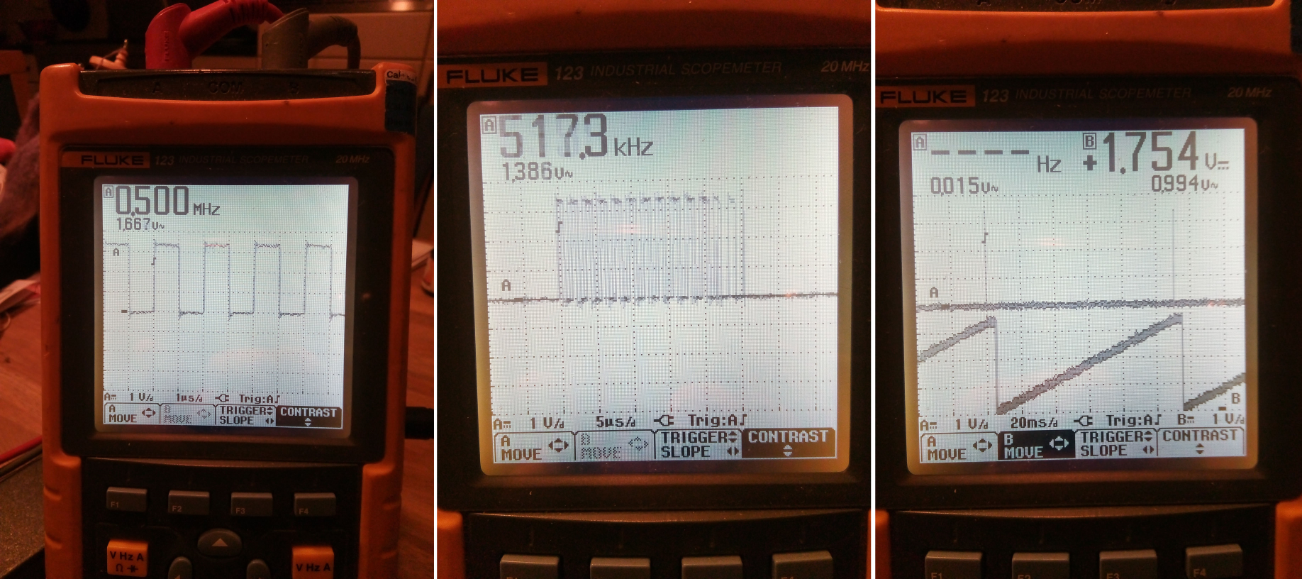
The first image is a continuous square wave of 500kHz, just to show how accurate the PWM frequency setting is (very accurate). the second shows the burst signal, which is slight longer than the 20 uS delay, probably because it also takes time to execute the command that switches it off. And the last image shows the linear ramp that starts 5 mS after the transmit. The ramp is linear, but it could be any shape, either from a formula or from a table.
Discussions
Become a Hackaday.io Member
Create an account to leave a comment. Already have an account? Log In.