 w_k_fay
I built two ring lights designs, a small 9v and a large 12v. They are powered by your garden variety wall wart with a current rating of 300ma to 500ma. Since everyone has a few wall warts kicking around this should help keep costs down and simplify the construction.
The power supply for both of the designs is a current limiting circuit using a LM317 voltage regulator. Light is provided by some 1w LED "beads". I harvested a couple dozen of them from some defective GU10 track light bulbs. If you don't have any LED "beads" on hand they are cheap and easy to get from eBay, AliExpress or some reputable source.
The small ring lights is designed to mount behind the 38mm B&L protection lens and use the protection lens as a retainer. It will also mount behind a 38mm B&L Barlow lens. The large ring light can be mounted behind the B&L protection lens or you can enlarge the center hole to accommodate a 48mm Barlow lens (or a camera adapter up to 56mm OD).
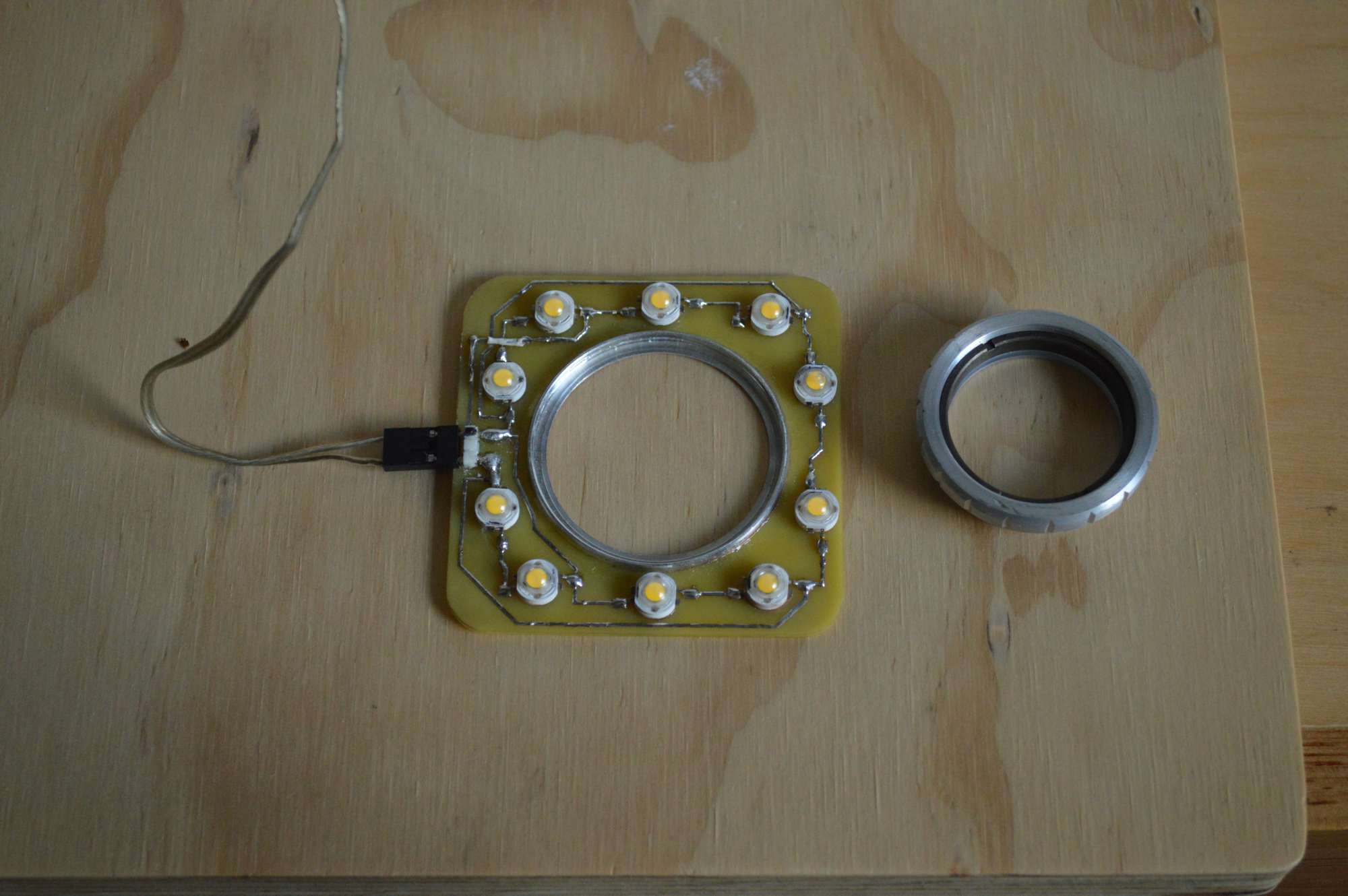
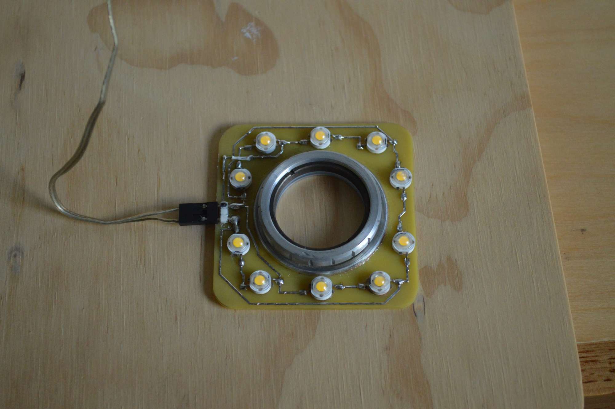 Above photos demonstrate how the small ring light fits behind the B&L protection lens. A header pin connector is soldered to the ring light and is connected to the external power supply by wires with DuPont connectors. You could just solder the wires directly to the ring light if you wish. Note the insulated wire used to make a board jumper in the upper left corner.
The aluminum ring in the center of the ring light came from the front of one of the track lights that I scrapped. It is glued to the circuit board with some thick C A glue. The track lights were purchased on eBay. You could also use a camera filter adapter in place of the aluminum ring and attach the ring light to your DSLR for macro photography. If you can't find an adequate substitute, double sided tape will also do the trick. I have some automotive trim tape that will hold just about anything in place permanently.
If you are uncomfortable with the exposed circuit board, you could place a piece of clear plastic over the circuit board. You might try a translucent white piece of plastic for glare reduction. Use my project as a jumping off point to create something of your own.
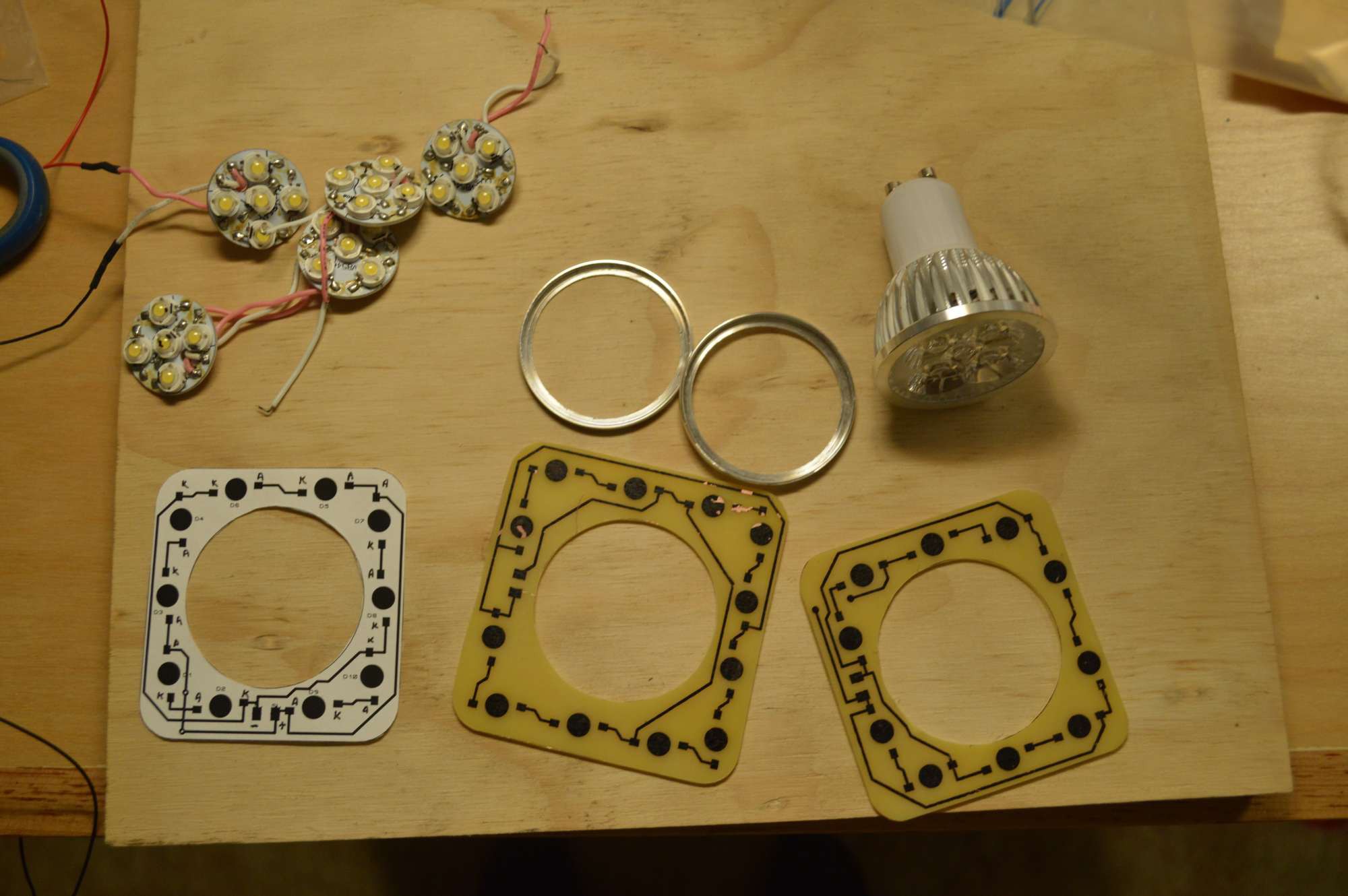
GU10 base track light and prototype ring light PCBs
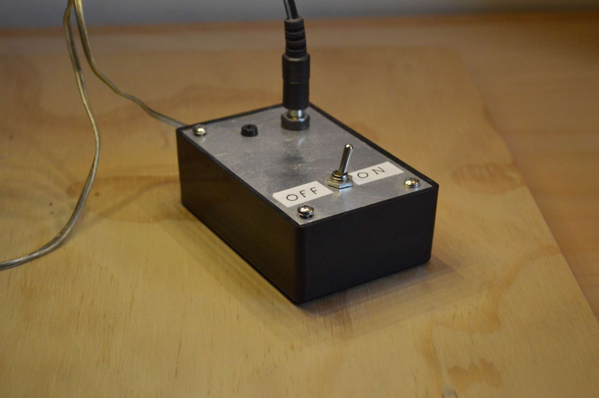
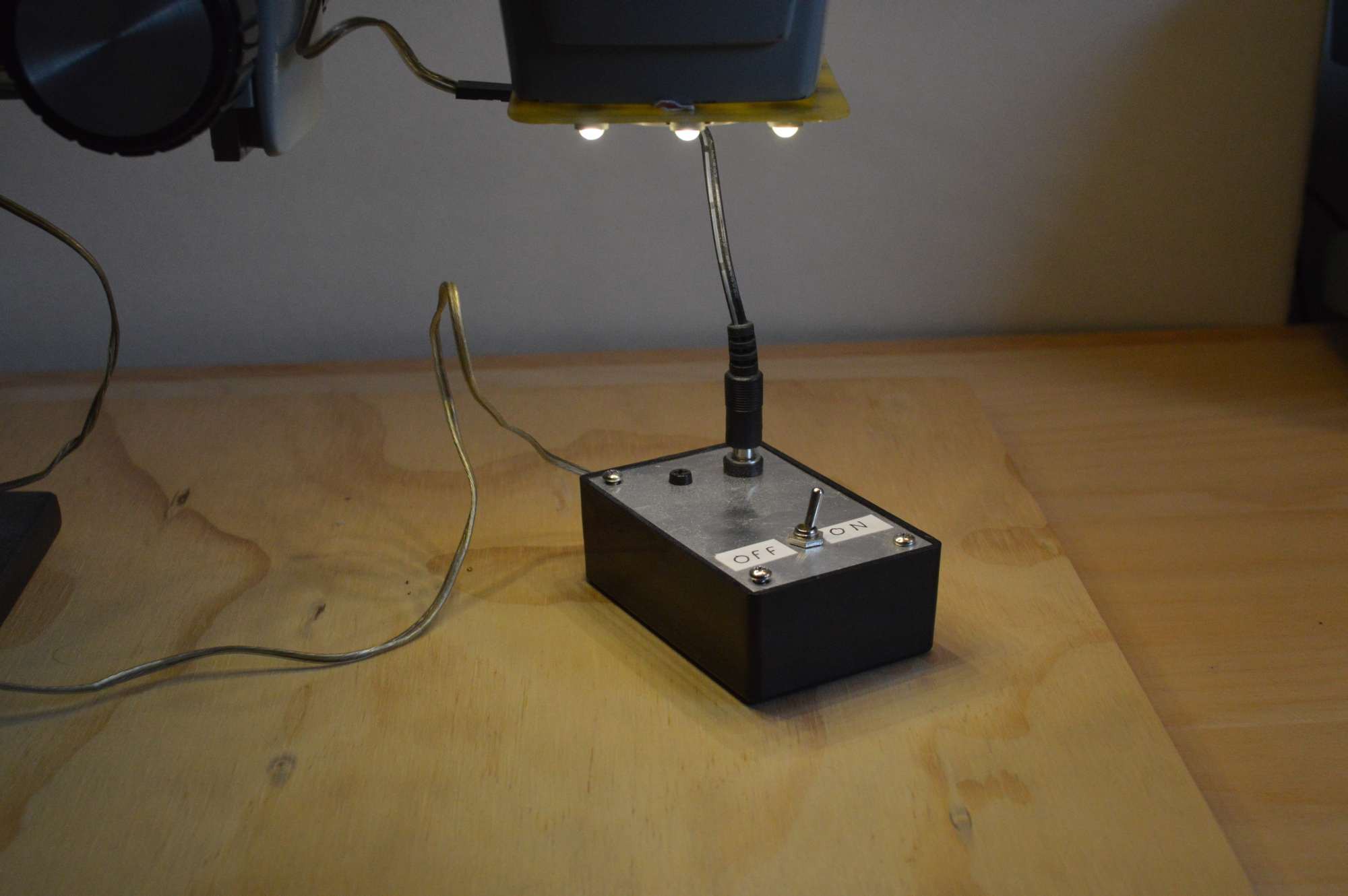
The current limiting power supply is mounted in the box along with a switch.
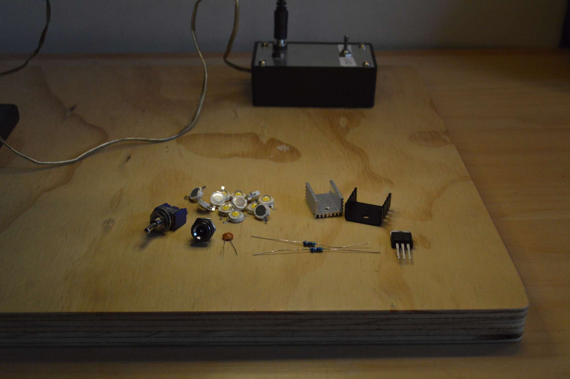
 The components used in the power supply
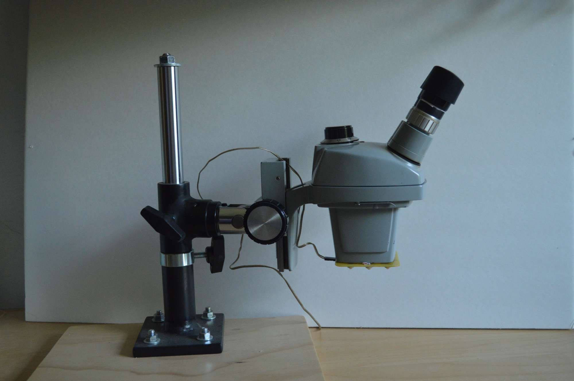
Small ring light mounted on the B&L StereoZoom 4 microscope.

Large ring light on another B&L StereoZoom
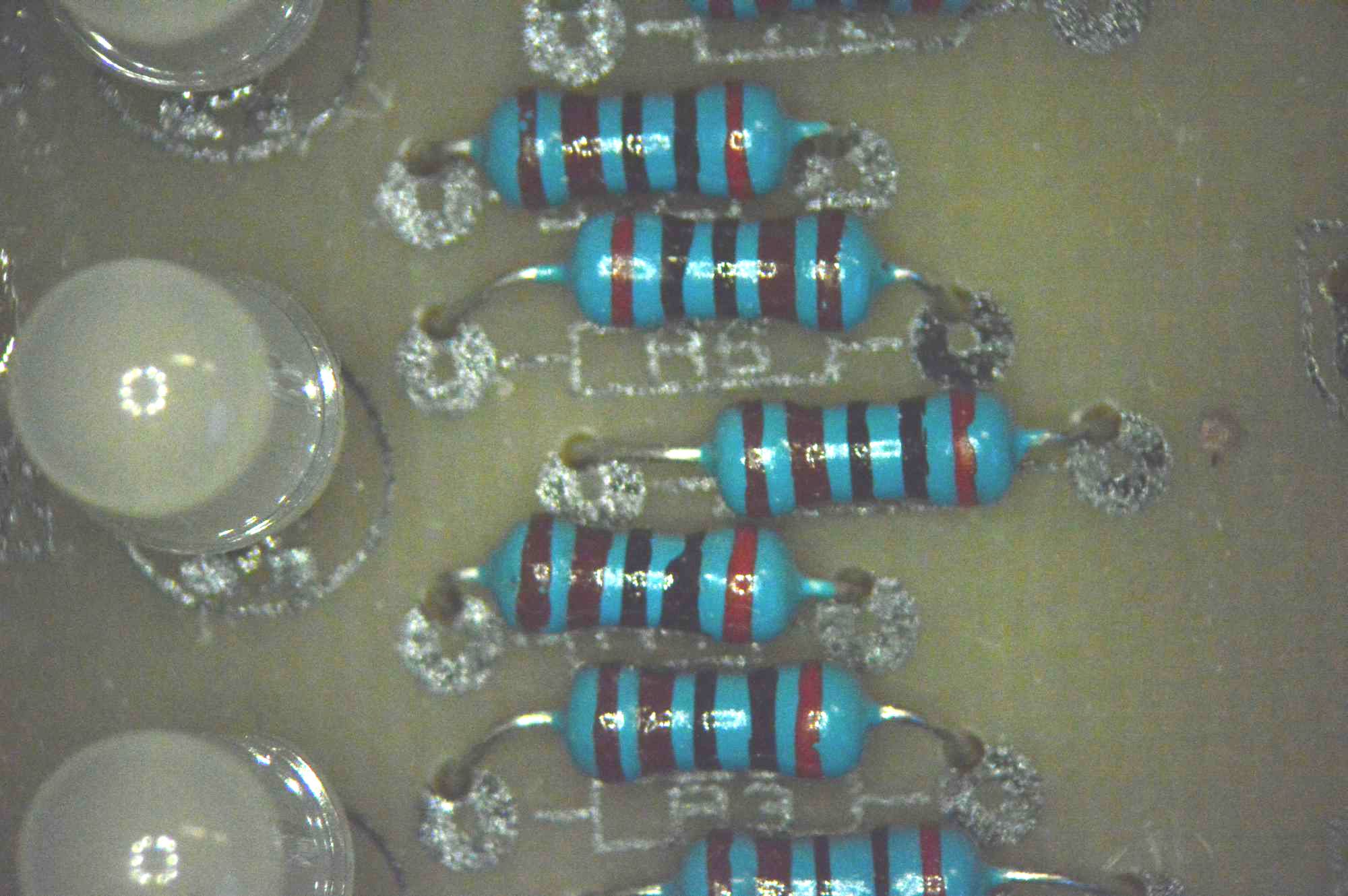
Photo taken through the microscope. You can see the ring light reflected in the LEDs.

This is the power supply circuit for both ring lights.
The power supply is a simple Lm317 current regulator. R1 and R2 are chosen based on the current requirements for each ring light. The regulator limits the voltage drop across R1 and R2 to 1.25v. The values for R1 and R2 and corresponding current outputs are shown in the diagram above. Two identical 1/4 watt resistors are used in parallel except for the 320ma output version that requires 1/2 watt resistors. You don't have to use two resistors in parallel. You could use any number as long as the resistance and wattage are correct. A handy online current calculator for the Lm317 can be found here : http://www.reuk.co.uk/wordpress/electric-circuit/lm317-current-calculator/
This circuit is so simple I built it on perf board, so there is no PCB for the power supply.
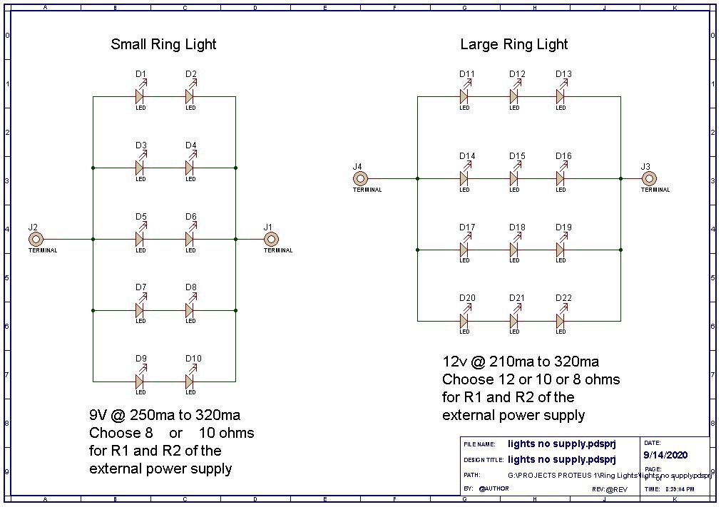
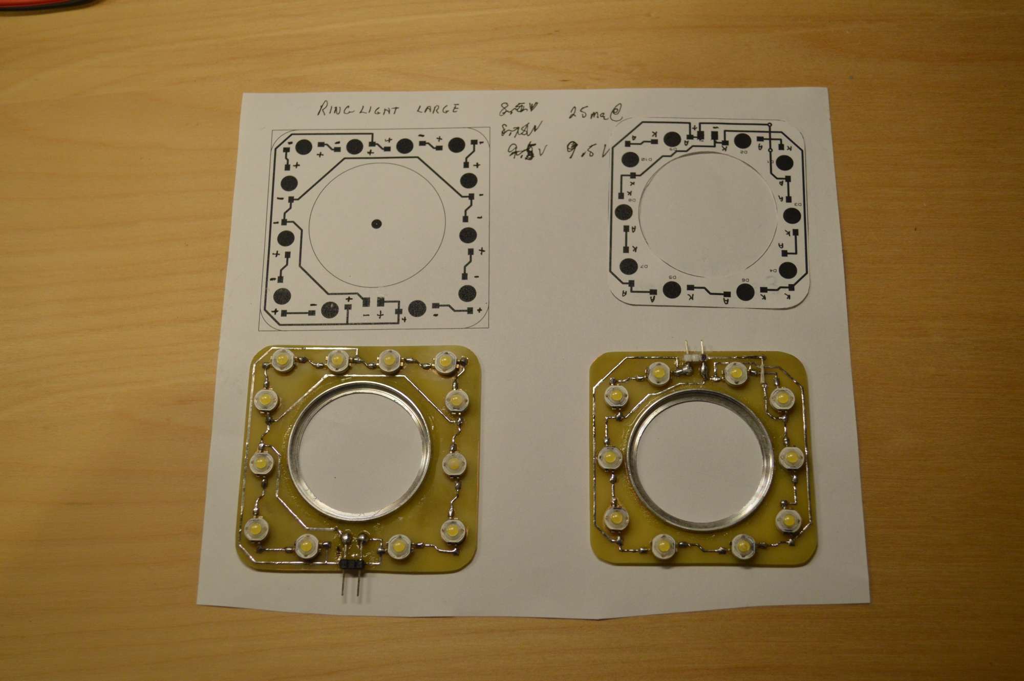
The circuit diagrams for both ring lights PCBs.
The small ring light has 5 rows with two LEDs in series and operates on 9v. The large ring light has 4 rows with 3 LEDs in series are operates on 12v. Current is calculated at 50ma to 75ma per LED. Divide the maximum current output of the power supply by the number of rows of LEDs to determine the current per LED. Make sure the current output of your wall wart is sufficient for the job.
The current is intentionally kept well below the maximum for a 1w LEDs so they stay fairly cool and don't require any heat sinking. Even at this low current level the light output is substantial. You can increase the current and brightness, but you may need extra heat sinking for the power supply and ring light. I found that above 100ma per LED heat becomes an issue.
The voltage calculations are based on a 3.5v drop per LED and a 1.5v drop for the linear regulator. These calculations allow a little bit of leeway to prevent the regulator from dropping out of regulation, which could cause brightness changes or flickering. You could use a wall wart with a higher voltage, but this would cause the Lm317 to dissipate more energy and get hotter. I won't go into great detail on linear regulators and power dissipation in this project, as I have written a detailed explanation in the Low Cost Power Supply Project. You can find that project in my projects section.
The small ring light has 2 LEDs in series for a 7v drop plus a 1.5v drop for the linear regulator totaling 8.5v. A 9v wall wart will produce the least amount of power dissipation in the regulator.
The large ring light has 3 LEDs in series for a 10.5v drop plus a 1.5v drop for the linear regulator totaling 12v. A 12v wall wart will produce the least amount of power dissipation in the regulator.
Both PCBs are in a RAR file in the attachments section.
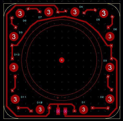
Component Map Small ** Note the orange jumper in lower left corner.
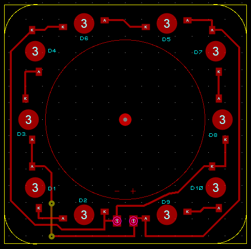
PCB small
Component Map Large
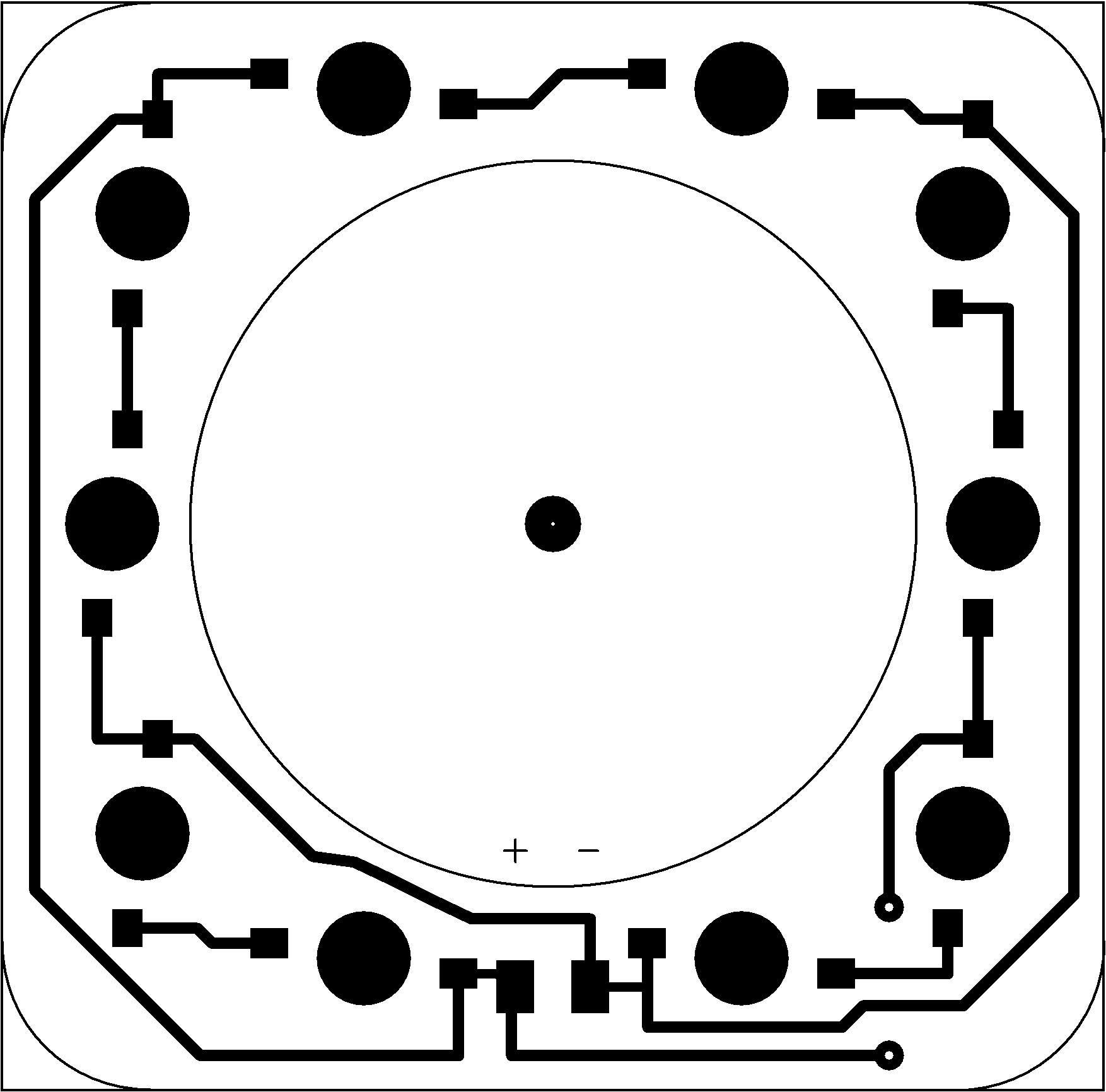
PCB Large
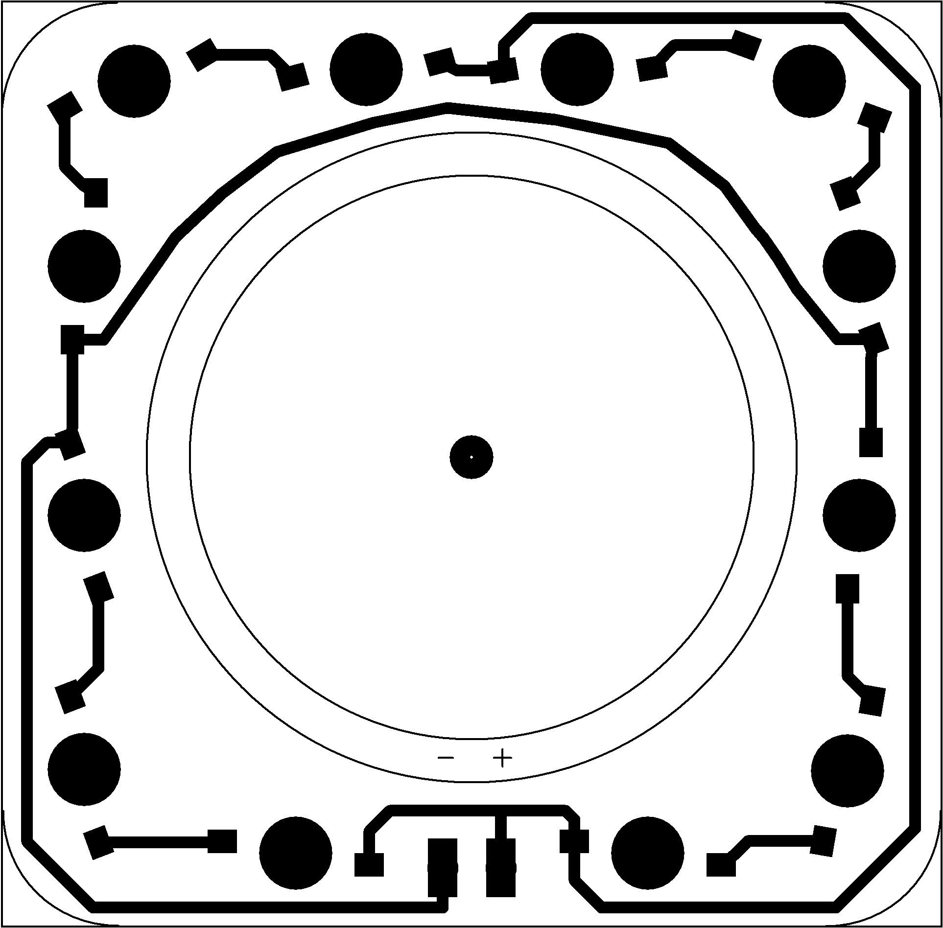
Print at 600 dpi (go to attachments section for RAR file). Use the component map to locate the anodes and cathodes of each LED. I put a tiny dot of heat sink compound under each LED. Note that the PCBs are reverse images because these are surface mount or top copper not the usual bottom copper for through hole circuit boards. They are ready to print on your laser printer at 600 dpi for toner transfer. If you are unfamiliar with making toner transfer PCBs I have covered this topic in another article in my projects section. It is best to print a test copy on plain paper and check a LED against the print to see if the printer is scaling correctly.
If you enjoyed this article or found it interesting a like or comment would be appreciated. If you build a ring light please comment about your experience with it.