The basic way to charge the capacitor is to switch an inductor. But watch out, there are lots of ways to blow things up!
Here is a basic schematic:
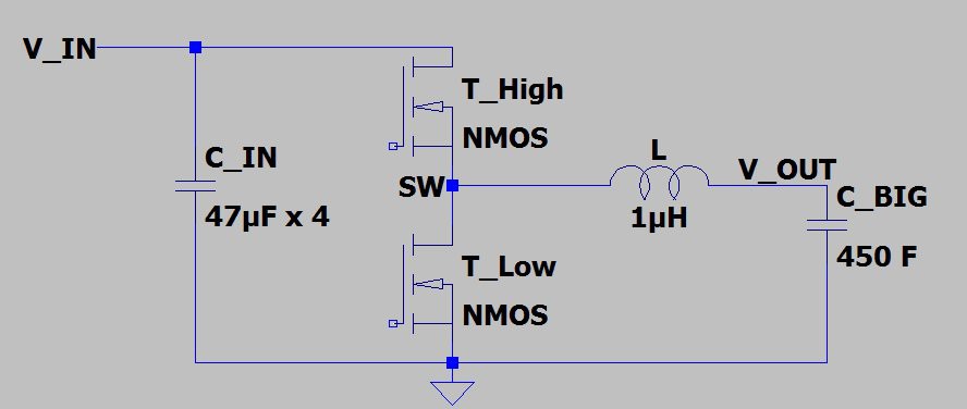
The input voltage is something like 12V. The transistors start with being off, so the input capacitor, C_IN, is also at 12V. You have to balance the selection of C_IN to reduce the ripple at the input, but it can't be too big, or else your 12V supply will be unstable.
Next, you *need* to protect your switching node, SW. If you aren't careful, this node will go extremely negative. This can happen if the inductor has current flowing through it, and you shut off the transistors. The body diode in the lower FET will turn on and the drop will pull SW negative. Some purpose-built ICs are allergic to this and will break. You can protect with a low drop Schottky, but watch out if you are trying to push a lot of current through the inductor.
You also have to be careful of having both transistors on at the same time. This causes crazy shorts. This can happen when you are programming the controller using the ISP (since this toggles most of the pins on the ATtiny13A - so you have to isolate the ATtiny13A during programming).
Also, note that C_BIG, is well, a pretty big capacitor. If you turn on the lower transistor T_low, and you don't have current flowing in to the capacitor, then current will definitely flow out of the capacitor back through the inductor, through T_low, to ground. The capacitor is not shy about dumping 287 amps through your circuit.
So, what is the big-picture idea for charging a supercapacitor? Here are the steps as I understand them. First, have the input capacitor charged up. Next, turn on T_high so that current starts to flow in the inductor to the supercapacitor. Next, turn off T_high, and then quickly (but not too quickly) turn on T_low so that the current can continue to flow through the inductor. Once the inductor current has decreased a bit, you turn off T_low, and then turn T_high back on so that the inductor current increases to make up for the decrease you just had. Then, you repeat, adjusting the on-time of the transistors to keep the current steady-ish.
Here is what happens when you first turn T_high, and just leave it on for a long time (5 us).
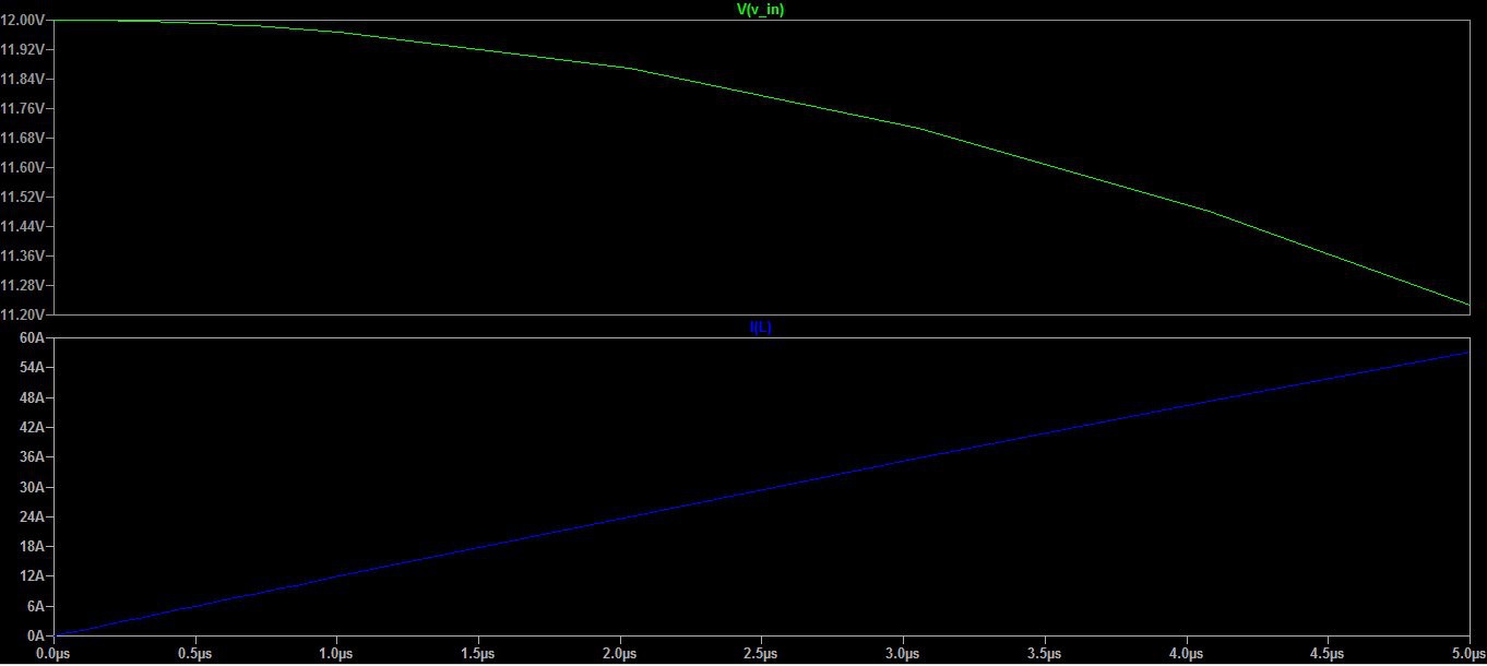
The input voltage local to the input capacitor starts to drop as the current builds in the inductor. Now, what I think is cool is that for a relatively small drop in the input voltage, you can get ~50A flowing in the inductor. In reality, you only want the transistor on for a bit so that each pass you slowly increase the inductor current to the set point.
Now, for the next step, and this is wacky. Let us say the supercapacitor has 0V (i.e., brand new, out of the bag, shipped with terminals shorted). If you turn on T_low, and just leave it on, this is what will happen:
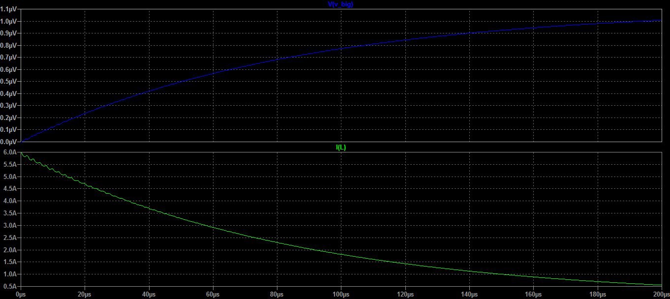
The inductor current just decreases nice and gently over ~200 us, slowly charging up the supercapacitor to ~1 uV. Now, contrast this with when the supercapacitor is already nearly charged (say at ~3V).
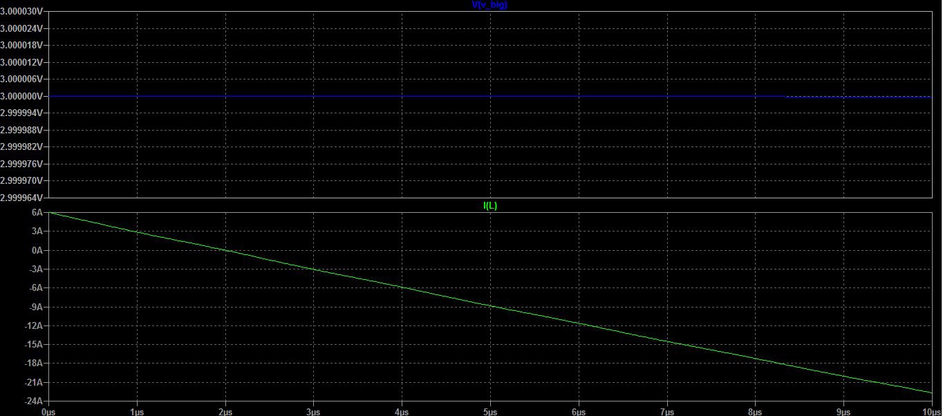
If you leave T_low on for longer than ~2us, then the supercapacitor will start to discharge (i.e., the current flow through the inductor becomes negative). I designed my controller to dither the on-time of the low transistor, so the controller has to be able to adapt to these two different time scales.
Discussions
Become a Hackaday.io Member
Create an account to leave a comment. Already have an account? Log In.