Here is the controller I designed. It is an ATtiny13A, 20 MHz external clock, and RC filters/resistor voltage dividers for the comparator and ADC inputs. I used the comparator to control the inductor current.
With 6 amps of charging current, 0.001 Ohm sense resistor, 200 V/V gain the current sensor, I get 1.2 V at the comparator input. With the ATtiny13A, I selected the 1.2V internal reference. So, based on the output of the comparator, you can tell if the current is too high or too low, and adjust the on-time of the lower transistor to compensate.
For the supercapacitor voltage, the max is 3V. I used a voltage divider to bring that under 1.2V, and used the ADC to measure the supercapacitor voltage, relative to the 1.2V internal reference.
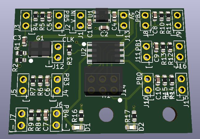
Here is the rendering from KiCAD:
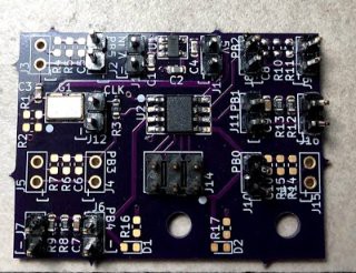
Here is the circuit populated:
PB0 is used to drive the high side transistor. PB2 is used to drive the low side transistor. PB1 is the comparator input to sense the input current. PB4 is the ADC input to sense the supercapacitor voltage. PB3 is busy receiving the 20 MHz external clock. The board accepts anything from ~5V up to 20V using an LDO (which also has reverse protection!)...yah SPX3819.
Discussions
Become a Hackaday.io Member
Create an account to leave a comment. Already have an account? Log In.