One issue I've often faced when debugging boards is scope probing. So, I usually include header pins with a dedicated ground at each place I'd like to view a signal. I prefer the through hole header pins to the surface mount because they are a bit more difficult to rip off of the board.
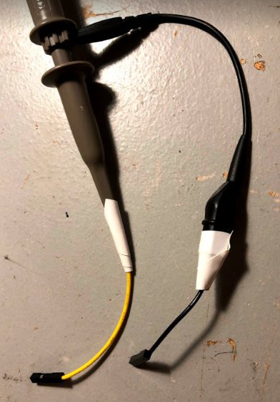
First, I prepare the scope probe. I take a header wire, connect to the probe, and then wrap with electrical tape. I do this for the signal line AND the ground line. I do this for the ground connection (usually an alligator clip) because I have been burned before when the ground connection pops off the connector and drags across the PCB, shorting stuff out as it goes. This method does add a bit of length to the path between signal and ground, but it is fast and a bit safer to move the probes around if you are trying to quickly check something.
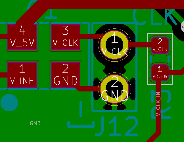
Next, in the board design, I made up a 2x1 header footprint, and include a "-]" text near the ground to give a visual reminder where to connect the ground. On my scope, the grounds are all common, so if you connect the ground to the wrong pin, you run the risk of shorting out something. So, I always like to have an extra reminder of where ground is. Below is "J12" (maybe should have called it TP12?), at the output of the 20 MHz clock.
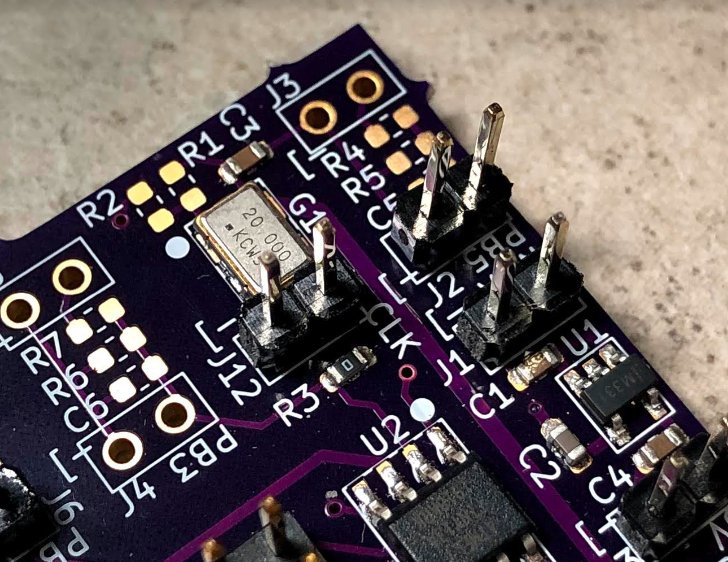
Below is the picture of the populated board, with the header ready for probing.
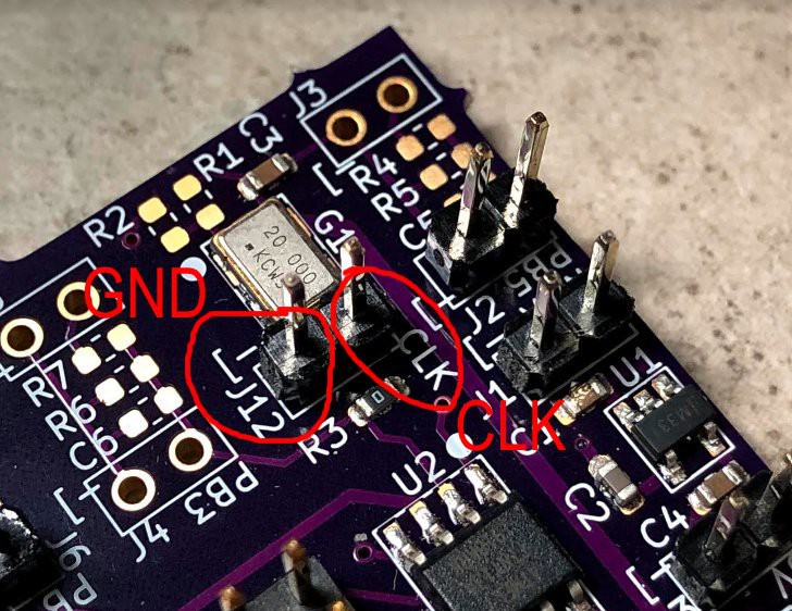
Here is the annotated picture of the PCB just to draw attention to the ground (GND) and clock (CLK) connections.
Discussions
Become a Hackaday.io Member
Create an account to leave a comment. Already have an account? Log In.