I've generally been running this circuit at 384x256 resolution, and that's how it's configured in the schematics. The main clock is 16MHz, but this is halved to 8MHz to from the pixel clock. It's divided down a couple more times to 1MHz to form the CPU clock, and the interleaved memory accesses also occur at that frequency. This is based on how the BBC Micro's video circuitry worked, and these timings match its "Mode 4", which was 320x256 (same timings, but a shorter line length for a non-widescreen display).
The BBC Micro also had a higher resolution 640x256 mode, "Mode 0". The way this worked was by doubling the pixel clock to 16MHz, and fetching from RAM at 2MHz. This also requires the CPU to run at 2MHz or more, as a 1MHz CPU needs access to RAM for too long at a time.
Unfortunately my 6502 CPU was a cheap clone and wasn't capable of running higher than 1MHz, so I wasn't able to get this doubling of horizontal resolution. However, since building the circuit I have got some WDC 65C02s that can run at much higher clock speeds, and this weekend I decided to go ahead and do the upgrade.
New pixel clock - 13.5MHz
Using a 16MHz pixel clock like the BBC Micro did is not a good option these days. Sometime around the turn of the century, when digitizing SD signals for display on TVs became important, the industry standardized on 13.5MHz for the pixel clock, for both 525-line NTSC and 625-line PAL. I verified this using an actual BBC Micro as well, to make sure it wasn't just a bug in my own circuit, and yes, it's blurry, and drawing certain patterns on the screen really confuses modern TVs!
So I sourced a 27MHz crystal and built a Pierce oscillator using it, then fed it into my existing circuit in place of the original 16MHz signal. The idea was to keep the pixel clock wired exactly as before - at half the core clock speed, which is now the desired 13.5MHz. Then the CPU would run at an eighth of that, i.e. about 1.7MHz.
Changes to video timings
The first concern is the video output signal though, rather than the CPU - even if the CPU isn't working, the video circuit should still display the random patterns in the RAM, which is handy as it allows you to solve one problem at a time.
All the horizontal timings are of course still fine - we don't want to change those, we just want to change the pixel output value more times per row. So we still count 2 half-rows per row, 625 half-rows per field, 6 half-rows for the vsync, and the same top margin (48 I think) and visible row count (256) as before.
However, all the horizontal timings, including the duration of a half-row, were previously measured against a 4MHz clock (divided down twice from 16MHz) and with a new base frequency, that would be off. So I had to calculate new values for all the counters in the horizontal timing section.
For example, the half-row duration for 625-line PAL needs to be 32us, which is 128 ticks of the 4MHz clock; the down-counters need to be configured with values one lower, so that was 127 before. Now that needs to be 32*6.75 = 216 ticks of the 6.75MHz clock (still divided down twice from the core clock).
Similar adjustments need to be made to all the other horizontal timings, as follows:
| Half-row | Horiz sync | Horiz Position | Horiz Duration | |
|---|---|---|---|---|
| Time (us) | 32 | 4 | 11.5 | 48 |
| 4MHz ticks | 128 | 16 | 46 | 192 |
| 6.75MHz ticks | 216 | 27 | 78* | 320* |
Values marked * have been rounded/tweaked a bit. Horizontal position is not critical, I rounded it to the nearest even number. Horizontal duration, at this frequency, is half of the number of pixels per row, and based on the old timing of 48us this would have been 324. However I only want 640 horizontal pixels, so this has been rounded down to 320.
Next though, 320 is too high because my down-counters are only 8-bit. Rather than add another counter, I just rewired that counter to be ticked at half the rate - i.e. 3.375MHz - and configured it for 160 ticks.
Note again that for all these cases, the value you configure into the down-counter needs to be one lower than the total tick count above.
Initial results
With those changes made, the results were pretty good - the CPU actually worked fine too, and I could see the last program I'd input running just fine. However there were some issues with the image - one was random noise appearing all over the screen, and another was address wrapping within each line causing the right side of the screen to display the same data as the left.
Fixing the noise issue
It took quite a lot of experimentation and tinkering to resolve the noise issue. Getting the relative timings right for the CPU and video circuit accessing the RAM was the hardest part of the original design, and with the frequency increase, the margins got smaller. The video circuit has less time allocated to access the RAM than the CPU does, and it was obviously feeling the pinch.
To output pixel data, I use a shift register, which loads up eight bits of data from RAM, then shifts them out one by one. After seven shifts, it's run out of data, so on the eighth tick of the pixel clock, it needs to fetch a new byte from RAM instead, and we also increment the video processor's address to move to the next byte. Outside of this period - i.e. for seven eighths of the cycle - the RAM address bus is connected to the CPU's address bus. So there's a relatively short space of time there for the RAM to get a new address to output from, to provide stable data on the memory data bus, and then for the shift register to load this new data before the address bus gets switched back to the CPU again.
Pixel clock phase
The first thing I tried was delaying the pixel clock relative to this period for which the bus is allocated to the video circuit. This led to a big improvement, but I couldn't delay it too much otherwise the bus would revert back to the CPU and the data being loaded would change.
Address increment timing
Another factor is the time at which the video processor's address counters increment. I'm using really slow ripple counters (4040BE) - they're convenient because each chip has something like 12 output pins, so I only need two of them to cover the whole 16-bit address bus - but as ripple counters, it takes a while for carries to propagate all the way up.
This one is much easier to solve - there's really no reason why the address can' be incremented way ahead of time. As soon as the bus goes back to the CPU, the address is not on the memory bus anyway. It's still best not to increment it straight away, but I found an easy way to increment it around halfway through the cycle, and that worked really well to remove the rest of the noise.
Fixing the image duplication issue
The other issue I mentioned was that the far right side of the screen contained a copy of a strip from the left. This was because I'd previously used a line-to-line stride of 64 bytes, for convenience. It was wider than the actual visible screen, before, but meant the maths was easy for calculating addresses from coordinates.
I also used two separate 4040BE counters - one for horizontal address, and one for vertical address - and the address bus bits were divided cleanly between the two. The vertical address was incremented by the end-of-line condition, and the horizontal address was incremented once every 8 pixels as noted above.
With a 640 pixel wide display, there are now 80 bytes displayed per line, which is more than the line-to-line stride. So after displaying 64 bytes of unique data, the 6-bit horizontal address wrapped to redisplay the first 16 pixels again at the end of each line.
I could have given the horizontal counter an extra bit, rounding the stride up to 128 bytes, but this would have meant using all 32KB of RAM for the video display, with a lot of wastage. Instead, I rewired the address counters so they're not split into horizontal and vertical - they're just wired in series so when one overflows, the other ticks up for the carry.
That worked pretty well, but it was quite fiddly to make sure there was never an extra tick at the end of a line. When this happened the rest of the image would get offset horizontally, and it wasn't always consistent frame to frame. I had to be quite careful with the tick timing, and this is why I made it happen halfway through the CPU's bus period rather than right at the start of it.
Updating the code to deal with the new stride value
I had to temporarily switch from hardware to software, to get a decent image after the counter change, because all my graphics coded assumed a stride of 64 bytes.
One case was working out the memory address corresponding to a location on the screen. With a stride of 64, it's easy to use a few shifts to work out what to add to the low and high bytes of the address. But with a stride of 80 it becomes harder. You need to add the value multiplied by 64, and then also add the same value multiplied by 16 - and both need to cater for carries into the high byte of the address.
The other main case to deal with was drawing text. The algorithm draws the character one line at a time, and needs to advance downwards first; but then at the end of the character, it wants to jump back to the top again. Advancing down was previously done by adding 64, which is easy to change to add 80. Going back up though used to just involve subtracting 2 from the high address byte; but now needs to do a proper subtraction of 640 from the two-byte address, with carry.
More image duplication problems
With that all fixed, I ran into another image duplication issue - now the bottom of the screen repeated the image from the top. The reason for this was that my video memory previously ran from $4000 to $8000 with 64 bytes per line, and 256 lines - but now it was 80 bytes per line, so the memory required went up from 16KB to 20KB. The last 4KB was taking the address beyond $8000, and it was wrapping back down to $4000 - so the first lines of the screen were displayed again at the end.
To resolve this I added a 4-bit adder to the top four lines of the video address bus, to define the start of video memory, rather than hardcoding it to $4000. That's now set to $3000, so it all fits snugly.
In the future I'll probably add more adders for the rest of the bus - or maybe switch to 4-bit presettable counters - so that I can dynamically offset the display for scrolling purposes. So this is a good change to have made for that reason too.
End result
So the end result is pretty good. I don't have the graphics routines written yet to show it off to its best, but here's a test card that I used to check the resolution and watch out for any glitches:

And here's the extra circuit I patched on to do this:
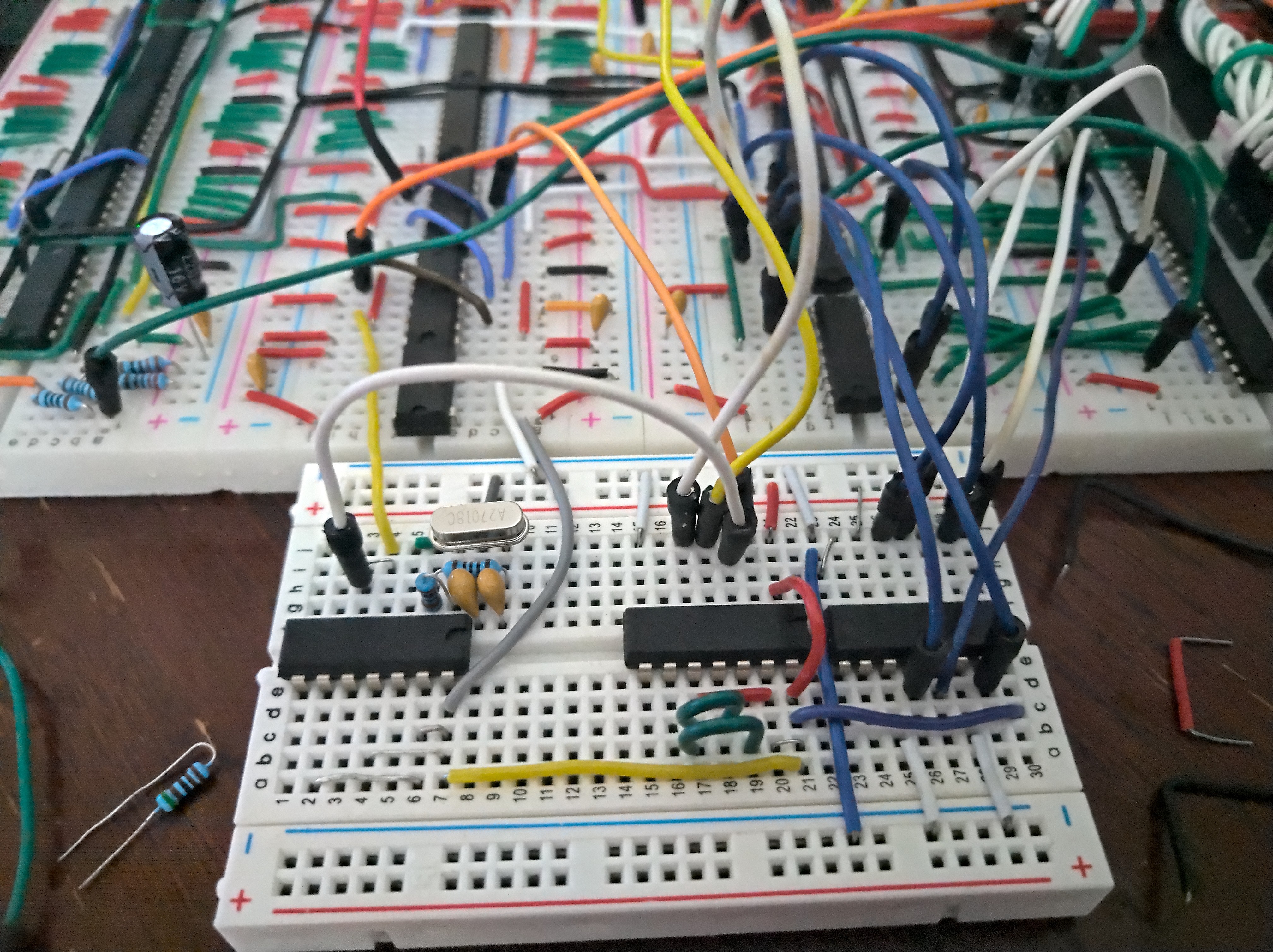
The chip on the left is an inverter, being used to form the Pierce oscillator with the 27MHz crystal. In the middle is a D flip-flop, used to help time the address counter increments. And on the right is the 4-bit adder which adds 3 to the high four bits of the address, to give a $3000 offset in memory.
I'm very tempted now to extend this to support 640x512 - it's already outputting an interlaced signal. In theory if the CPU changed the video memory content every frame then it would already output 640x512 - but that's a lot of data for a 6502 to update in a short space of time. So I really need to arrange for enough RAM to be available to store the full 512-line image. That's going to need 40KB, which is too much for the current 32KB RAM chip. I could swap it for a 512KB RAM chip but it might not be fast enough - the 32KB chip has a fast 15ns access time. So I might need to add a second 32KB RAM chip for that. We'll have to see how that goes.
Discussions
Become a Hackaday.io Member
Create an account to leave a comment. Already have an account? Log In.