Electrical and software part:
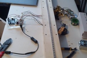
The Arduino controller is used in our prototype, as neither the LEGO Mindstorms nor
HUSARION controllers were available for us. Two of the buttons simulate limit
switches, and the third one is an user button. Diodes represent the movement of the
gate - green diode is the upwards movement, and the red one is downwards. Diodes
are connected through the serial 470 ohm resistor from the Arduino digital ports (13
and 12) to the anode and from cathode to the ground (Arduino’s GND). All of the
input ports (11, 10 and 9) are grounded via the 10k ohm pull-down resistor to provide
stable work. User button is used to open or close the gate, depending on it’s position
or previous motion; for example - if the gate is moving upwards, after clicking the
button it will stop. When we click again, it will start moving downwards. It is
designed to achieve convenient utility. In the real doors, where we would use DC
motors instead of LEDs, the circuit would need to be modified - instead of diodes, we
could use NPN and PNP transistors or relays, connected properly to the DC motor, with a
proper symmetrical power source (e.g. +-24V or so), to ensure proper power to lift the
gate. In such a case we might need to modify the mechanism, adding the reducing
transmission, to achieve proper torque. External power source is crucial, as the maximum output
current of the arduino is around 200mA, so connecting the motor (even a 5V servo!)
would most likely result in burning the port or even a whole microprocessor. So we
use it to ensure a proper current source.
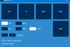
The program is simply written with the use of some if statements. The wanted functionality is:
- the user uses only one button
- if the gate stands still, the button activation will move it
- if the gate is moving, activating the button or reaching maximum position (open or close) stops it
- after stopping, the gate will always move the opposite direction
For example: gate moves upwards, we stop it with a button, again move it with a button, the gate moves downwards and reaches limit switch and stops. The next button activation moves it upwards.
The source code can be found in "Files" section.

 st0chastic
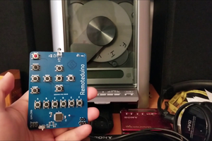
 sjm4306