 Kevin Kessler
This project will run off a Lipo battery, which means the voltage will vary from 4.2 V to about 2.5 V. This voltage is well outside the range of the ESP32 and other chips on the weather station, so I build a buck/boost converter to keep the supply voltage at 3.3 V, regardless of what the battery voltage is.
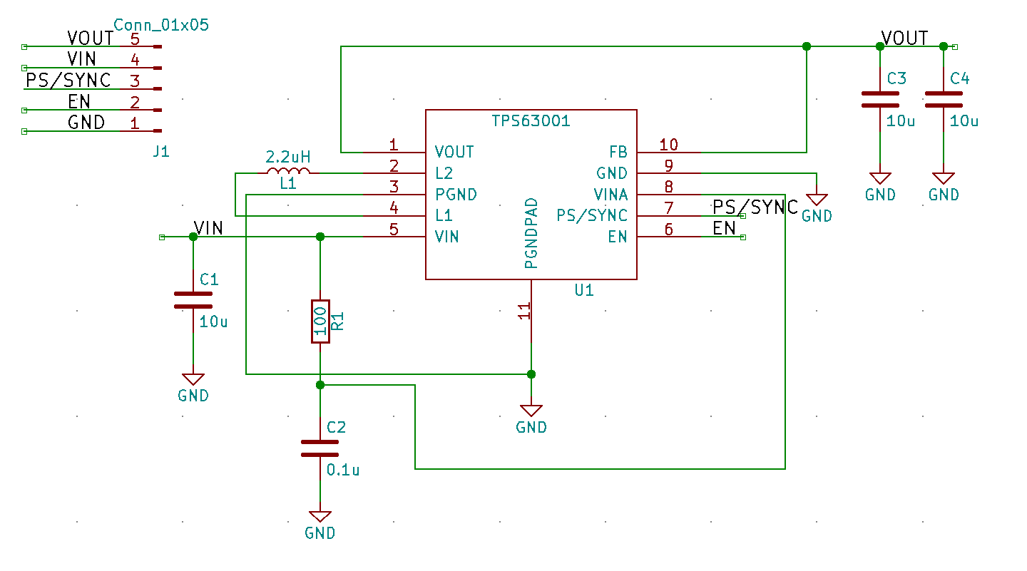
I originally based this supply on the TPS63001 from Texas Instruments. It is a fixed 3.3 V buck/boost converter and this is the schematic I created:
And this is the PCB.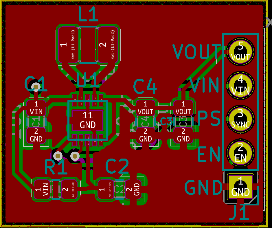
The TPS63001 is a truly painful chip to solder, being a WSON package, with no leads that extend from the chip's body; the leads are just (very small) pads that sit under the chip. I decided I would get the board made by JLCPCB, and try out their SMD assembly service, so I wouldn't have to deal with that buck/boost converter package.
Unfortunately, they were out of stock of the TPS63001, but they did have the lower current, pin compatible TPS63031 , so I substituted that IC. One thing to note, while I didn't have to change the PCB layout for the replacement converter, I did have to make the PCB slightly larger, since the SMD Assembly service's minimum PCB size was 20 mm square.
I was quite pleased with the SMD Assembly service, although the first PCB I fired up and gave 3.3 V initially, it then almost immediately stopped working. I spent a good bit of time trying to understand what I did wrong, until I just grabbed another board, and it worked fine.
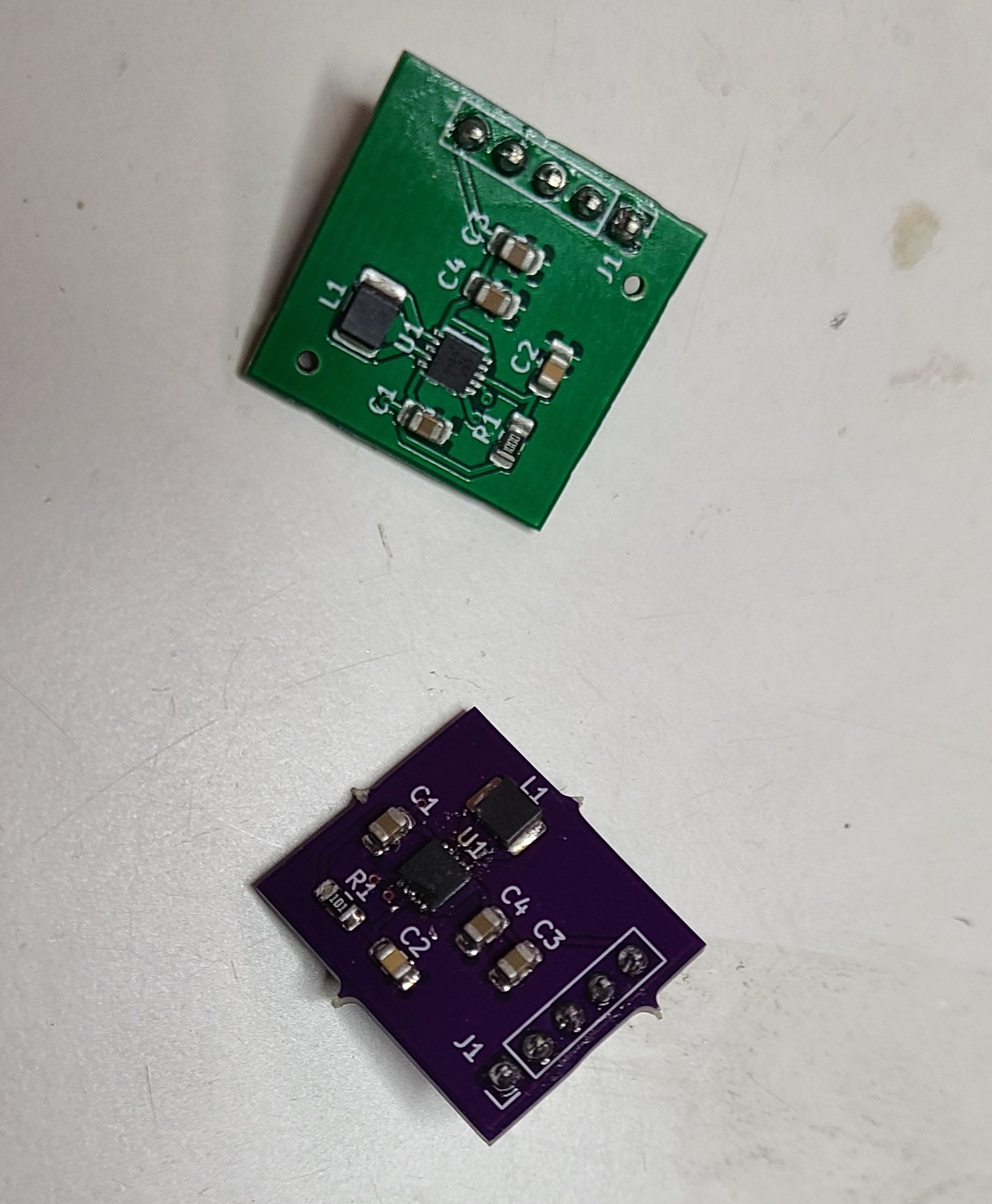
I decided to also have OshPark make me a set of 3 boards on which I would solder the TPS63001 on, so I could compare the 2 chips.
On top is the JLCPCB assembled PCB, and the purple board at the bottom is, of course, the OshPark PCB.
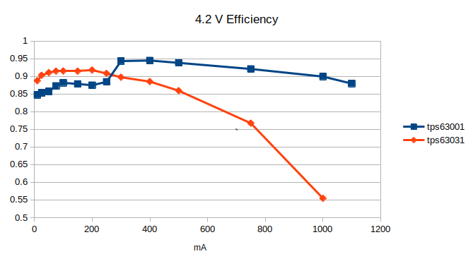
I plugged both boards into my Maynuo electronic load to find out how the TPS63001 and TPS63031 fared at various input voltages and output currents. I would measure input power and output power to calculate how efficient the converter was, and I found that, at low currents, I was getting more power out than I was putting in. While I was dreaming about winning the Nobel Prize, I decided to hook the current meter up to the Maynuo, and I found it current setting had a bit of an offset. At the 10 mA setting the Maynuo was really only drawing about 8 mA, and the 2 mA offset was consistent across all the currents I was testing. My tests were no longer breaking the laws of Physics with this adjustment.
At 4.2 Volts on the input, the TPS63001 was able to source 1.1 A of current before the output voltage dropped precipitously, while the TPS63031 gave up at around 750 mA. More importantly for this project, though, was at less than 300 mA, the TPS63031 was more efficient, converting over 90% of the input power to output power.
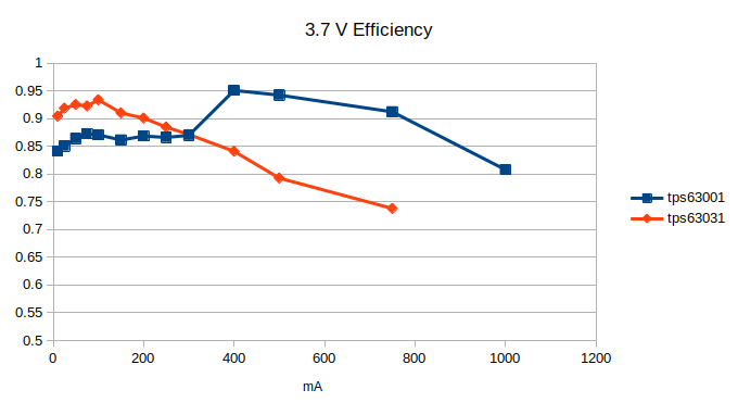
At 3.7 Volt s input, the pattern held, with the TPS63001 being able to supply 750 mA, while the TPS63031 could only supply about 500mA, but in the current range of this project, the TPS63031 was more efficient.
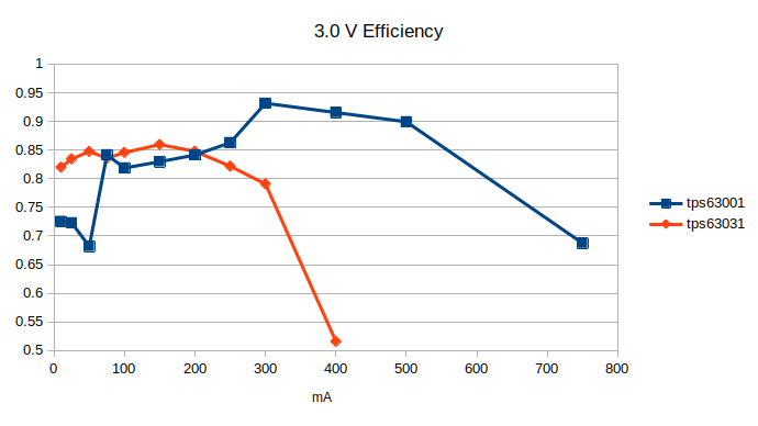
At 3.0 V, the TPS63001 was able to supply 500mA, while the TPS63031 was only able to get to about 350ma, but once again, it was the efficiency winner for most of the current range of interest.
With 0 current draw, the TPS63031 also bested the TPS63001 with a quiescent current of about 68uA compared to 80 uA. In order to get this low Iq, you must set the PS pin on both chips to low to put it in Power Saving mode. This allows the chip, under low current conditions, to basically shut off for long periods, at the cost in about 100mV in ripple. Since that doesn't affect the ESP32 when it is sleeping (and adding a bunch of capacitance helps mitigate that), it is a price worth paying, because without power saving mode, the quiescent current is about 3 mA, and too high for a battery operated circuit.
Since it performed better in the current ranges that this project will draw, I decided to go with the TPS63031.
Discussions
Become a Hackaday.io Member
Create an account to leave a comment. Already have an account? Log In.