In the area of electrical projects, there is a specific area that develops lighting projects. This area is called Luminotécnica.
Once the lighting is dimensioned, it is necessary to execute the project and then carry out the luminosity measurement to check if it meets the criteria established in the lighting project.
To perform this measurement, a device called Luximetro is used.
Therefore, in this article, you will learn how to develop a Luximetro using the BH 1750 light sensor with the Arduino Nano and a 16x2 LCD display.
Therefore, through this article you will learn:
- 1 - Perform the circuit assembly on the protoboard;
- 2 - Understand how the BH1750 sensor works;
- 3 - Perform the communication of the Arduino Nano / Arduino Nano the BH1750 light sensor;
- 4 - Display of measured values on the LCD display;
- 5 - Develop your NEXTPCB Printed Circuit Board.
The project will be developed in partner with NEXTPCB and you can access the printed circuit board files and earn 10 FREE PCBs through the link: NEXTPCB Printed Circuit Board.
Now, we will start the complete presentation of the development of the Luximetro project with BH1750 sensor.
Developing the Luximetro Project with the BH 1750 Sensor
As previously mentioned, the project consists of creating a system to perform the luminosity measurement using the BH1750 luminosity sensor.
The BH1750 I2C Brightness Sensor
With the BH1750 light sensor, it is possible to measure the light intensity in the range from 1 to 65, 535 Lux.
This sensor has I2C communication, which facilitates communication with microcontrollers, since it uses only 2 pins, an SDA data pin (serial data) and SCL clock pin (serial clock line), in addition to the VCC and GND power pins.
I2C communication uses the concept of master/slave, in which the microcontroller is the master and the peripherals as sensors, displays are the slaves.
The microcontroller is responsible for sending the clock signal to the I2C bus so that data is sent by the peripheral.
The SDA pin is a pin that has bidirectional communication, because sometimes it sends information, sometimes it can receive information.
The advantage of using I2C communication is that it is possible to connect several devices on a single bus to read and send information, each device occupies a different address on the I2C bus.
The sensor its the following characteristics:
- Power Supply of 3.3V ~ 5V;
- Digital Output Signal;
- Measuring range of 1 lux ~ 65535 lux
The sensor image is presented below.

Figure 1 - BH1750 Sensor Pins.
In figure 2 we have the schematic circuit with the necessary connections for assembling the project.

Figure 2 - Schematic circuit with the connections of the BH1750 sensor and the LCD display to the Arduino nano.
After assembling the electronic circuit, we will program the Arduino Nano to communicate with the sensor and display the values on the LCD display.
Development of the Luxmeter Programming
To program the Arduino Nano to communicate with the BH1750 sensor, we will need the Wire.h library (performs I2C communication) and the BH1750 library.
 // Bibliotecas #include <Wire.h> #include <BH1750.h> #include <LiquidCrystal_I2C.h> LiquidCrystal_I2C lcd (0x27,2,1,0,4,5,6,7,3,POSITIVE);
 // definiçao de objeto BH1750 sensor; void setup() {  // velocidade de comunicação serial  Serial.begin(9600);  Wire.begin();  sensor.begin();  Serial.println(" Monitoramento de luminosidade sensor BH1750 ");  lcd.begin(16,2);  lcd.setBacklight(HIGH);  lcd.setCursor(2,0);  lcd.print("LUXIMETRO");
}

void loop() {  // variavel para leitura da luminosidade  unsigned lux = sensor.readLightLevel();  lcd.setCursor(2,1);  lcd.print("LUX: ");  lcd.setCursor(6,1);  lcd.print(lux);    Serial.print(" Luminosidade: ");  Serial.print(lux);  Serial.println(" Lux ");  delay(300);  lcd.clear();  lcd.setCursor(0,0);  lcd.print("SENSOR - BH1750");
}
The BH1750 library can be downloaded through the Arduino IDE, in Sketch and added libraries.
The Wire library comes with the Arduino IDE by default, we will need to add the BH1750 library responsible for communicating the sensor with the Arduino Nano.
Inclusion of the Wire, BH1750, and LiquidCrystal_I2C libraries, libraries responsible for carrying out I2C communication with I2C devices, and libraries that have specific functions to communicate with the BH1750 sensor (BH1750) and to write on the 16 x 2 LCD display (LiquidCrystal_I2C).
// Bibliotecas
#include <Wire.h>
#include <BH1750.h>
#include <LiquidCrystal_I2C.h>

Definição do objeto do display lcd 16 x 2 I2C e do objeto do sensor BH1750
LiquidCrystal_I2C lcd (0x27,2,1,0,4,5,6,7,3,POSITIVE);

// definiçao de objeto
BH1750 sensor;
After defining the objects of the LCD display and the BH1750 sensor, we go to the void setup function.
In this function, the I2C bus, sensor, and display are initialized, configure the Arduino serial communication speed
Configure the display model with 16 columns and 2 lines, write the message on the display.
void setup()
{
// velocidade de comunicação serial
Serial.begin(9600);
Wire.begin();
sensor.begin();
Serial.println(" Monitoramento de luminosidade sensor BH1750 ");
lcd.begin(16,2);
lcd.setBacklight(HIGH);
lcd.setCursor(2,0);
lcd.print("LUXIMETRO");
}
Now, let's go to the void loop function.
In the void loop function, we read the sensor and display the measured values on the LCD display.
With the functioning sensor.readLightLevel () we read the BH1750 sensor and store it in the lux variable.
void loop()
{
//variavel para leitura da luminosidade

unsigned lux = sensor.readLightLevel();

lcd.setCursor(2,1);
lcd.print("LUX: ");
lcd.setCursor(6,1);
lcd.print(lux);

Serial.print(" Luminosidade: ");
Serial.print(lux);
Serial.println(" Lux ");

delay(300);

lcd.clear();
lcd.setCursor(0,0);
lcd.print("SENSOR - BH1750");
}
After programming the Arduino Nano, we can view the measurements shown on the display as shown in figure 3.

Figure 3 - Project constructed with Arduino, 16x2 LCD, and sensor BH1750.
Now, you'll learn how to create a NEXTPCB printed circuit board for this project.

Figure 3 - 3D View of the Printed Circuit Board.
This printed Circuit Board was developed from of electronic schematic presented below.

Figure 4 - Electronic Schematic of the circuit.
After this, was developed a layout of the Printed Circuit Board. Finally, we'll develop an enclosure to put a printed circuit board, install the sensor, and buttons for future new projects.
Developing an enclosure for the Project
An enclosure was developed to put the circuit. You can use a laser cutting machine to cut your plywood and assembly your project through screws.
You can use a screw of M2.5 with a length of 12 mm. Below is presented the enclosure in 3D View.

Figure 5 - Enclosure to put the Printed Circuit Board.
Next, you can access the structure of the enclosure in a laser-cut file. Below are present each part of the project of an enclosure.
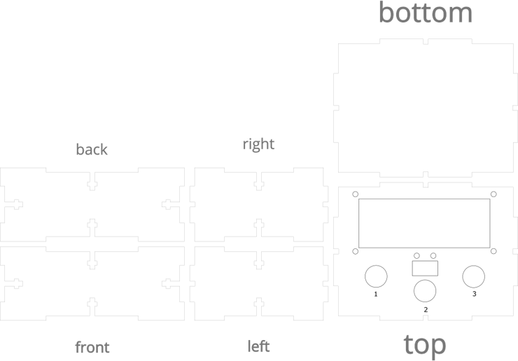
Figure 6 - Laser cutting files to assembly the enclosure.
The file presented above is available in PDF file in this project.
With the parts you assembly and run your project.
Acknowlegment
We appreciate the support of NEXTPCB for supporting, developing and offering 10 free units to all readers of this article through the link: Obtain NEXTPCB Printed Circuit Board.
We would also like to thank the Robô Lúdico School in Brazil.