 Jerry Isdale
Arduinos are good microcontrollers for dealing with hardware (read sensors, write to effectors). TouchDesigner (TD) is a fabulous tool for making cool videos and sound animations. There are some simple examples available that show how to send/receive one or two values between these tools, but not a lot to show how to share more items. This project show how to use an arduino compatible to send multiple data items to TouchDesigner and control an animation.
The Adafruit Circuit Playground Express (ACPE) is an excellent entry board for learning to work with Arduinos as it comes integrated with several components. This allows beginners to focus on coding and avoid avoiding the issues with wiring and mounting sensors, etc. It has on-board an 3-axis accelerometer, light sensor, two momentary and one slide switch, temperature sensor, sound sensor, 10 neopixel multicolor LEDs, 7 pads for capacitive touch, as well as I2C, SPI and other connections. It is fairly easy to have the Arduino read its connected sensors and send them to other computers via standard Serial USB connections.
TouchDesigner (TD) is a very powerful, a node based visual programming language for real time interactive multimedia content [wikipedia]. For over 20 years it has provided a base for artists to create impressive interactive installations, performances and other works. There are lots of tutorials and examples on the web. TD provides a node for reading and writing to Serial (USB) devices, and the wiki includes simple examples of how to connect with an Arduino
The available examples, however, are quite simple; reading only one or two sensors and responding to a single command. The ACPE has so many built in sensors and there isnt a lot available on how to send such to TD. It can also do a fair bit with outputs but this project is only going to focus on inputs from Arduino to TouchDesigner. Perhaps a later project will build on this for controlling lights, sounds, etc via Arduino from TD. Code (both arduino ino and .toe files for TD are available in the GitHub for this project.
Arduino Side:
Basic Arduino use is covered extensively elsewhere. Adafruit has a good tutorial introduction to their ACPE board. Lets assume you have it setup and working with your PC (or mac). Arduino programs have two primary functions setup() and loop(). For this project they are pretty simple. Setup initializes the Serial communications and then a pair of calls are made to the Adafruit CircuitPlayground library, begin() and setAccelRange(). The former sets up the library to run, and the latter tells it we are using the finer 2G resolution for accelerometers (+/-1G). The second function may be the default but it wont hurt to specify it.
void setup() {
  Serial.begin(9600);
  CircuitPlayground.begin();
  // set for small accelerations, good for tilt sensing +/- 1G
  CircuitPlayground.setAccelRange(LIS3DH_RANGE_2_G);
}
The loop() function reads the sensors and sends them to the Serial port. The code reads a number of sensors but for this round, it only sends out the 3 accelerometer values and two calculated values for Roll and Pitch. This snippet shows the start of loop() reading a four values. The code repo is more elaborate.
void loop() {
  //first we grab data from CPExpress...
  // not doing capactive touch yet
  X = CircuitPlayground.motionX();
  Y = CircuitPlayground.motionY();
  Z = CircuitPlayground.motionZ();
  leftSwitch = CircuitPlayground.leftButton();
Calculating Tilt:
The board does not provide tilt measurements directly, but under normal gravity you can derive the Roll and Pitch values from the three accelerations. Details of this are explained in a couple nice application notes, one from NXP and one from ST. You can get elaborate with it but basically it is a pair of trig expressions:
  roll = atan(Y / sqrt(pow(X, 2) + pow(Z, 2))) * 180 / PI;
  pitch = atan(-1 * X / sqrt(pow(Y, 2) + pow(Z, 2))) * 180 / PI;
Sending Data as Comma Separated Values:
Comma Separated Values (CSV) is a very common way to save and share multiple values. It is a simple text file format often used with spreadsheet programs. We will use it to export the data items from the Arduino. Creating CSV streams is a bit cumbersome with Arduino as it lacks a formatted print function. This because memory is at a premium in many Arduinos and elaborate formatting functions take a lot of space. So we make do with two function calls per variable we want to output. The first Serial.print() function prints the variable, and the second outputs a comma. After we have printed all the variables on a line, we use Serial.println() to terminate the line. Again this snippet shows only the main values for now. Code repo has more
  Serial.print(X); Serial.print(",");
  Serial.print(Y); Serial.print(",");
  Serial.print(Z); Serial.print(",");

  Serial.print(roll); Serial.print(",");
  Serial.print(pitch); Serial.print(",");

  //...

  // lastly terminate the line/message
  Serial.println();
Lastly the loop() function calls delay() to pause for a short while. The current delay is for 50ms and can be adjusted as desired. Note that the accelerometer can give a fair bit of jitter. Some smoothing could be added here in the Arduino code, or filters could be added later in TouchDesigner.
  // slight pause between sends
  delay(50);
}
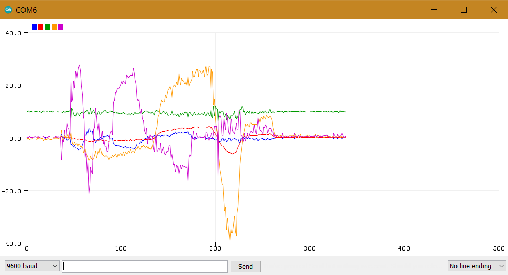
thats it for the aduino code. If you load the program to the ACPE, you can use Tools>Serial Plotter to see the data graphed. This image shows a couple roll/pitch and then sitting quietly on table:
TouchDesigner
If you are not familiar with TouchDesigner, watch a few tutorials, starting with First Things To Know About TouchDesigner. Initially, I was going to use some more elaborate examples with generative images/geometry, however, to keep things simple, I stayed with the default project. This is the one you see when you open TD.
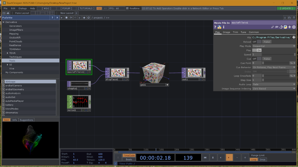
This loads a movie file, displaces it with some noise, and texture maps it onto a cube. Pretty simple. We modify it by adding several Nodes to read and process the serial data from the arduino and use the roll/pitch to control rotations of the cube.
Note the top two nodes are simple sine channel that can be used to rotate the cube without using the arduino.
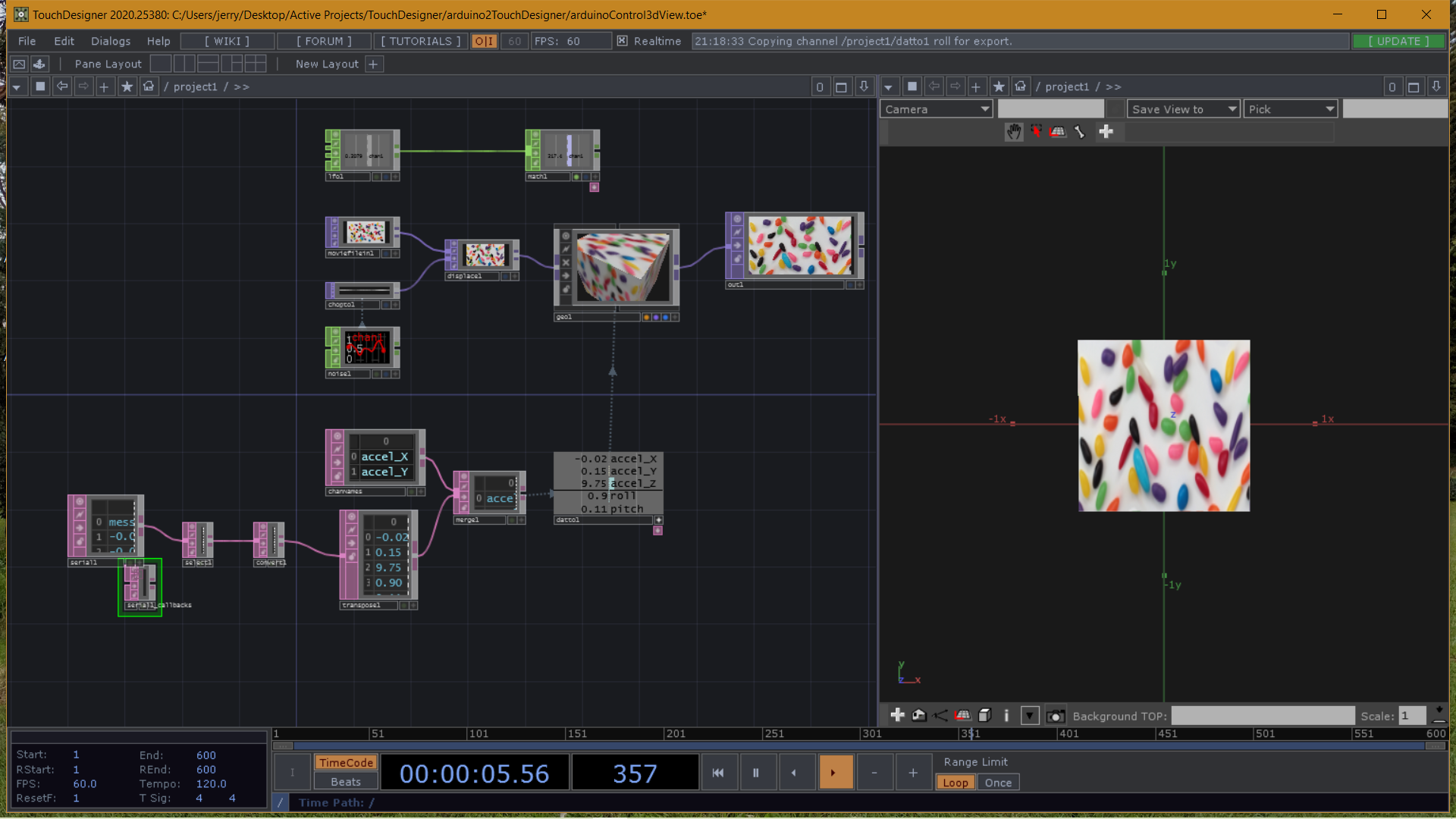
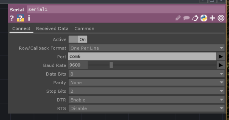
To connect to the arduino we need a Serial DAT. Double click to bring up the Node list, go to DAT tab and click on Serial. This drops a new node and opens its Parameters. If the Parameters are not displayed, use P key to toggle display. Check the Port parameter matches the port to which your Arduino is connected. Once connected, it should start streaming data into node.
Next add a SelectDAT and connect it to the output of the SerialDAT. We will use this to select the first row only. Set SelectRows to "by Index" and both StartRow and EndRow to 1 (first row says "message"). We want all columns
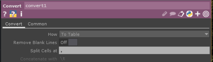
Next we add a ConvertDAT to the output of the SelectDAT. Change the "Split Cells at" to a comma (,). Note we could alternatively print at tab (\t) instead of comma back in the Arduino program... or a space or whatever you like. Comma is just common. Th is node will expand the single column CSV message into however many columns are present, filling out the table.
Next we add a TransposeDAT to the output the ConvertDAT. This turns the single row into a single column. This is needed to conform to the way TouchDesigner sees Channels of data... as individual rows with columns being the successive values. No parameters need be tweaked here.
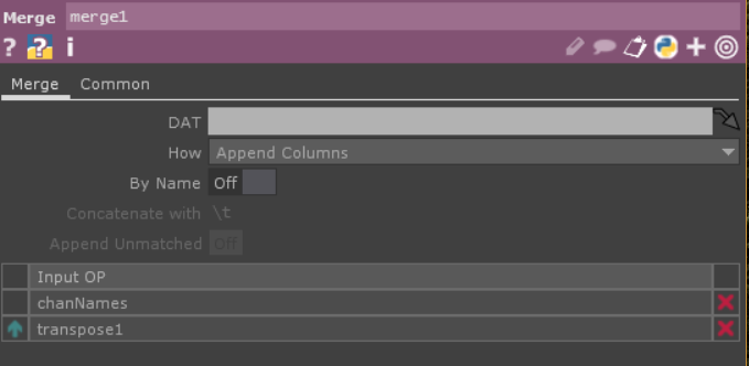
We are going to want to label the channels for reference. For this simple exercise it isnt necessary but later you will want the names. To do this we add a TableDAT, edit it, and put one name per line. Be sure the order of names match your Arduino's order of variable Serial.print() functions. Staying with single word names for channels, usingCamelHump or other method. Then add a MergeDAT and connect the top input to the TableDAT and the lower input to the TransposeDAT. Set the "How" parameter to "Append Columns".
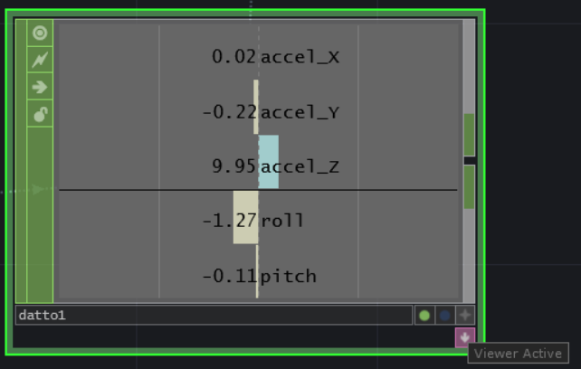
Next we add a DATtoCHOP from the CHOPs and connect its input to the Merge. You can leave it to Select Rows as All or select only the rows you want to convert. For columns, start at 0, and end at 1. This gets the label and latest value. Set Output to Channel Per Row. Set the First Column to Names. Then on the node, in lower right, click on the + to make the Viewer Active.
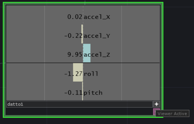
Now click on the GeometryDAT and display its parameters. Drag the roll channel from the DatTo active view to the Rotate X parameter and the pitch channel to the Rotate Y parameter. You will only be able to drag them if the DatTo is viewer is Active.
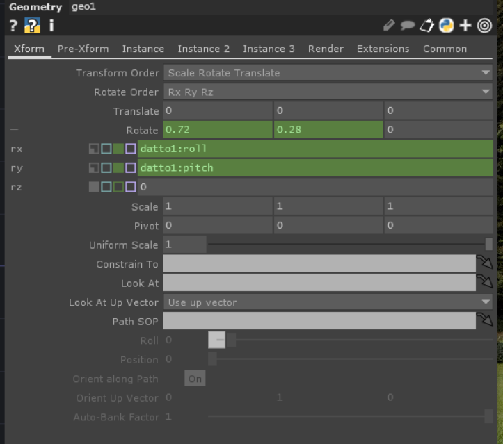
Now when you rotate the ACPE arduino, the cube will rotate. Note the direction of rotations may not be quite what you expect, and it may lag or jitter a bit. Those we can take care of later.
You could use similar techniques to connect other values from the Arduino to other parameters of nodes.
Later updates to this project may look at adding sensors like switches, and sending commands from TD back to the arduino (changing delay, lighting LEDs, etc)