 P
PUpdate 1 (9/25/20): Just came across this guide from Frank Seel that has a lot of good info for upgrading the ender 3 for dual extrusion:
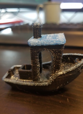
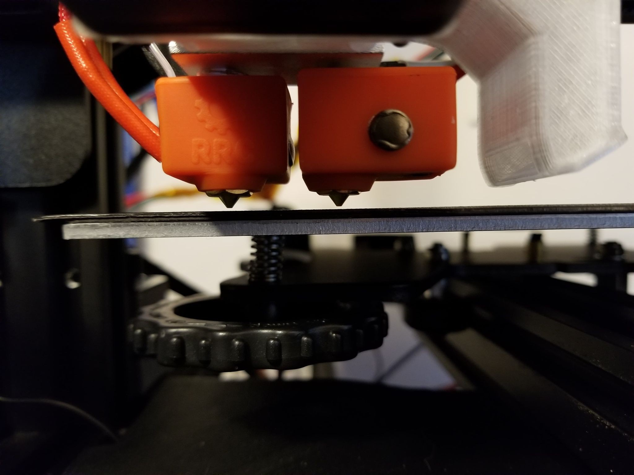
Update 2 (9/29/20): Have been having issues with both nozzles clogging after the first few layers. After retightening the nozzles, checking the tubing length into the hotend, etc., I figured it's not because of any slop in the hotend assembly. I think it is a result of some of the standby settings Cura uses which retracts and cools the unused extruder while the other is in use. This seems to make a plug in the retracted filament that then won't extrude if the settings are non-optimal (similar to the issue in this thingiverse post: https://github.com/Ultimaker/Cura/issues/5432). After raising the standby temp from 175°C to 205°C and drastically reducing the nozzle switch retraction distance from 16mm to 3mm the clogging issue has resolved, although the inactive nozzles ooze more now so it seems these settings need more tuning to optimize.
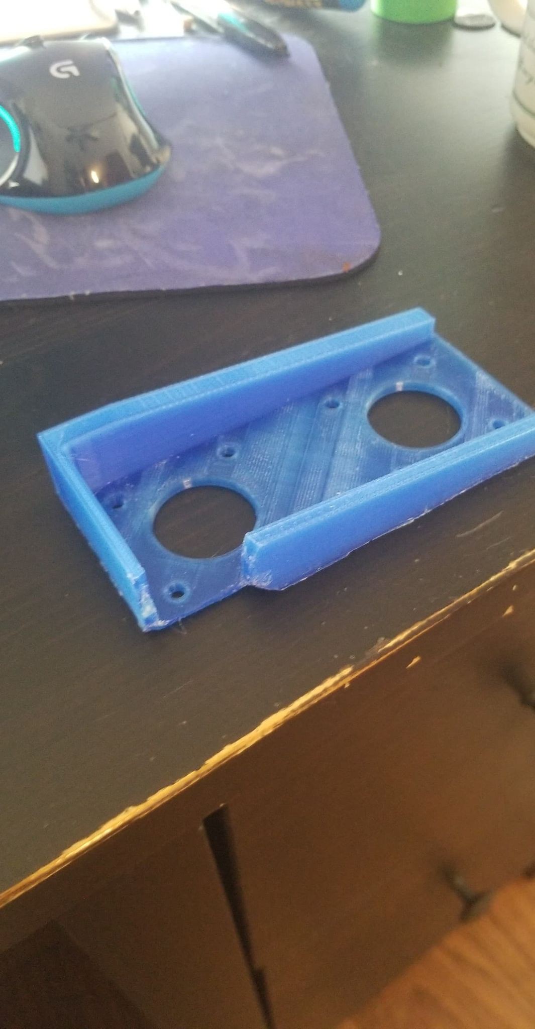
Update 3 (9/30/20): I was still getting some partial clogging and underextrusion, especially with a translucent blue PLA filament, while the black filament was printing fine, regardless of which nozzle was used for each filament.
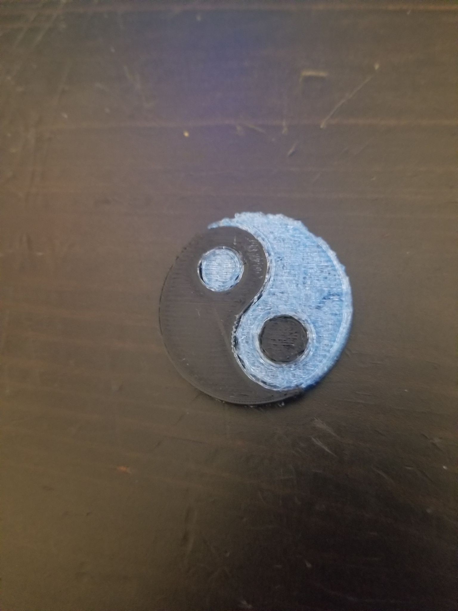
Examples of translucent blue filament under-extruding:
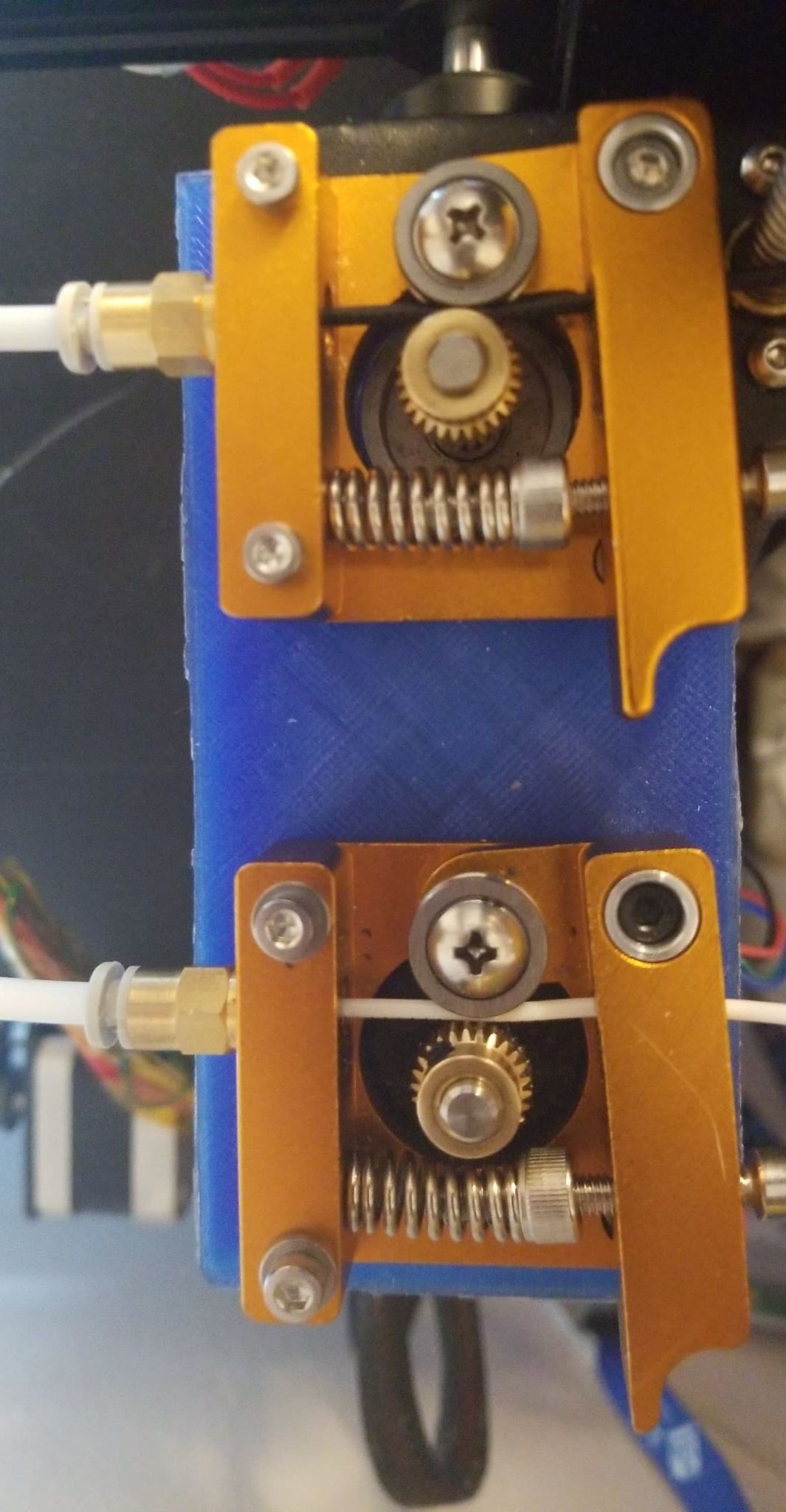
I realized the spring in the extruder block is supposed to be installed in a different manner so that it could be compressed more by tightening one of the supporting screws. After making this change, and adding some additional force to the extruder bearing, the filament is being keyed a lot deeper. I also switched to some white filament, and haven't noticed the under-extrusion issue anymore, so it may have been something about the blue filament (It seemed like even by hand the blue filament was harder to extrude). I'll try the blue filament again with the tighter extruder block spring and see if I still have the under-extrusion issues.
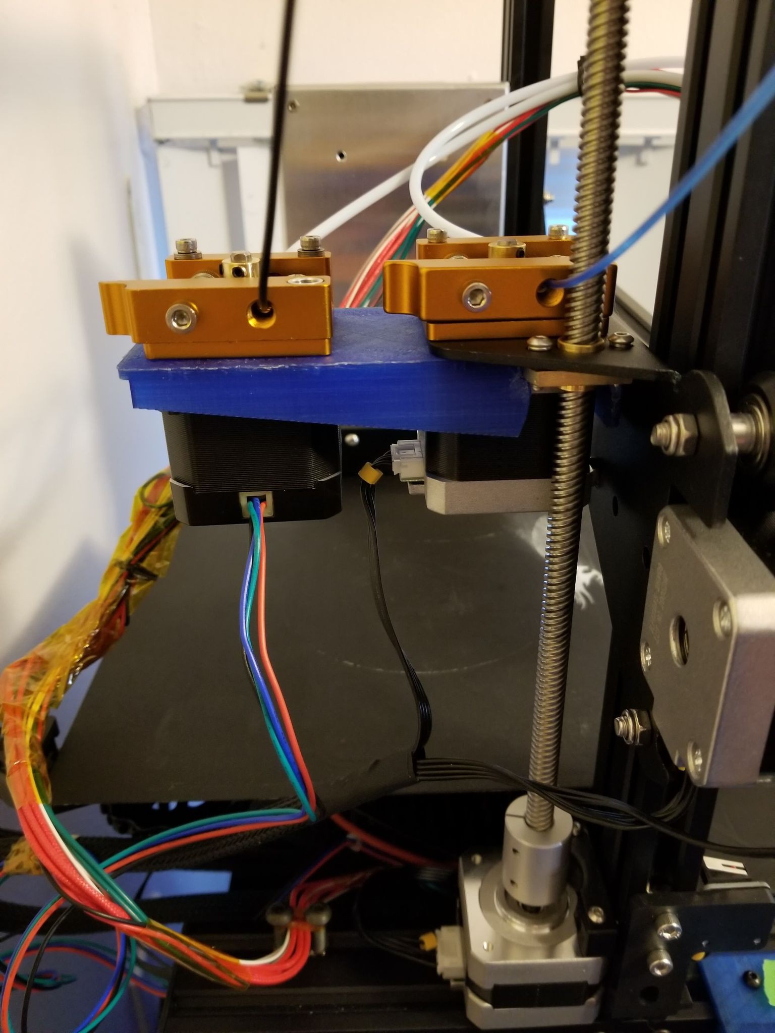
Tightened extruder block springs:
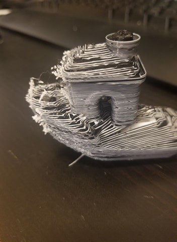
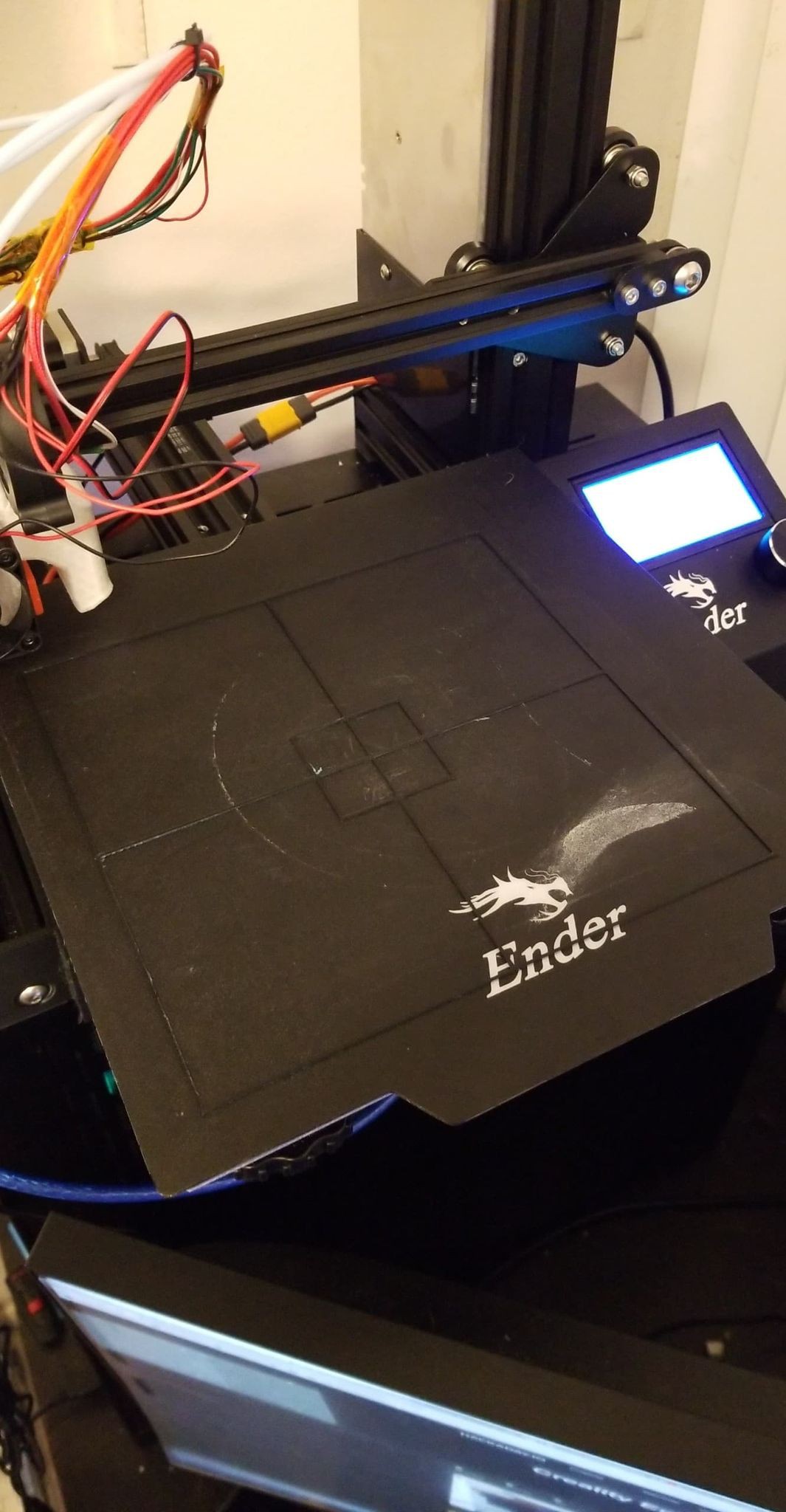
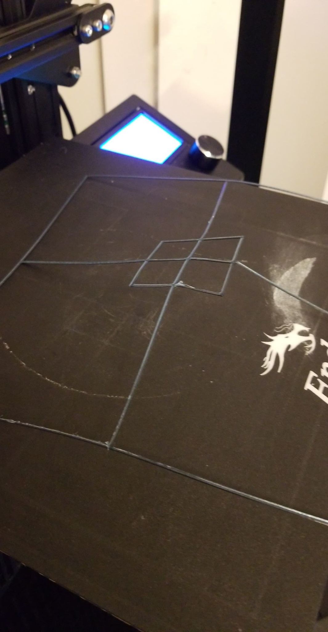
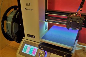
 Ooze shield doing it's job:
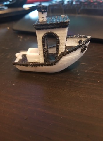
Voila:
Update 4 10/4/20:
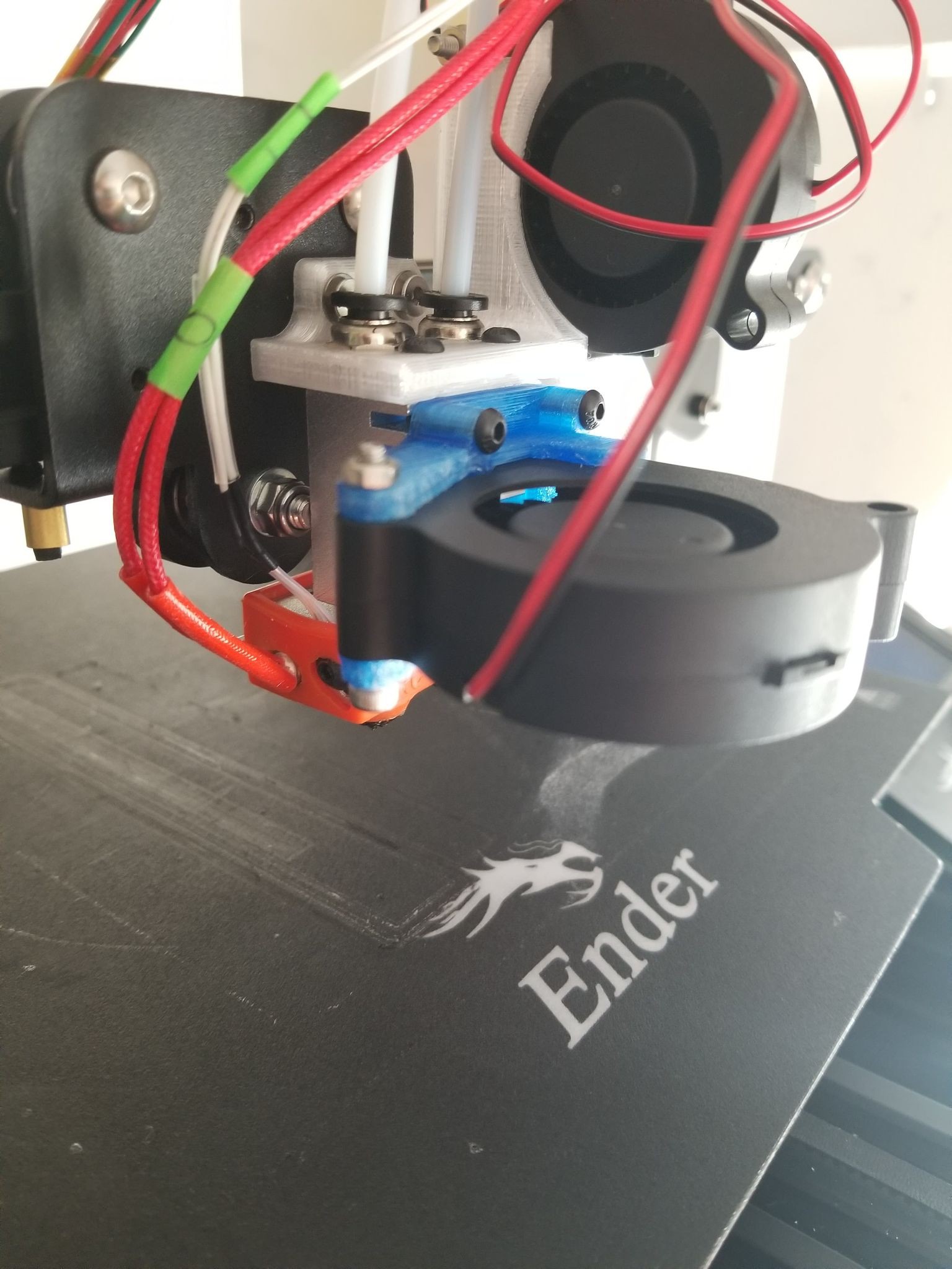
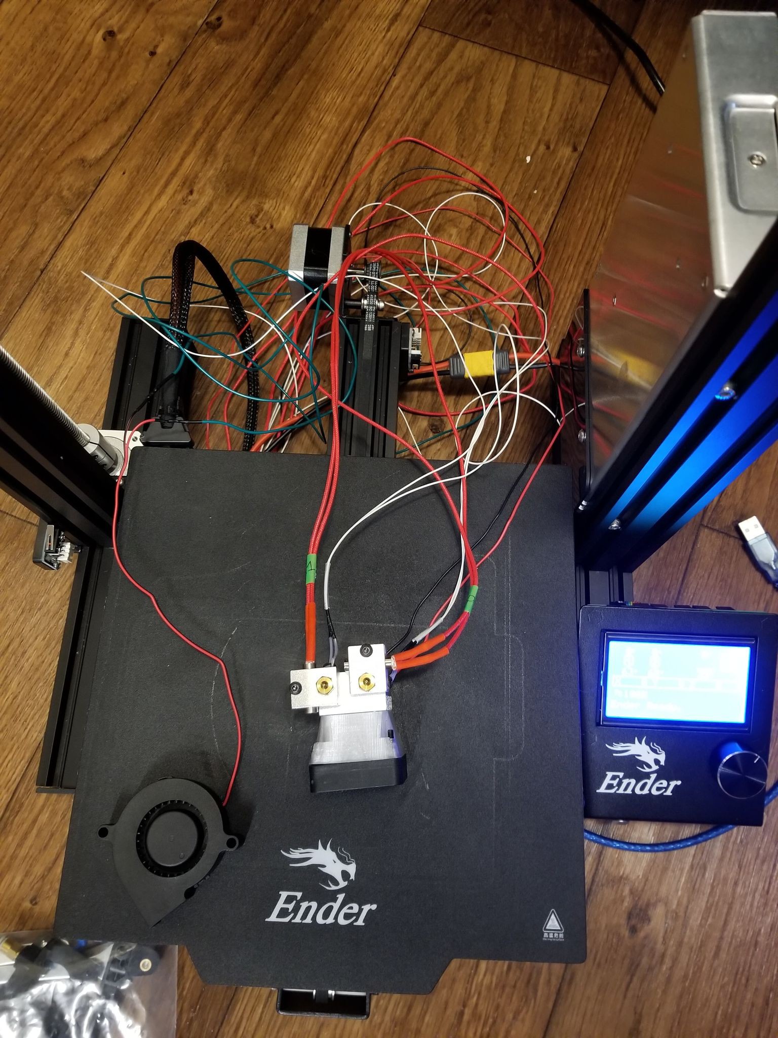
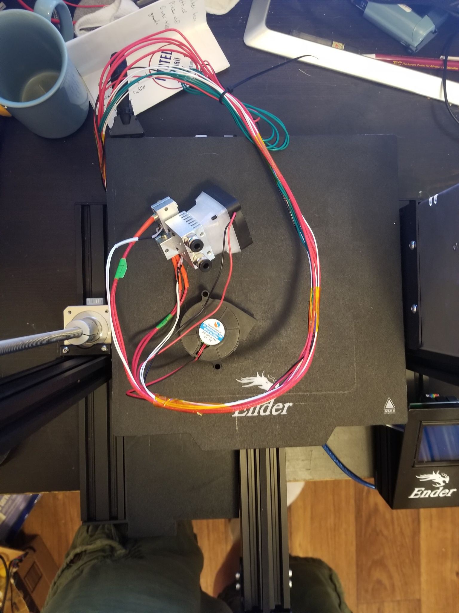
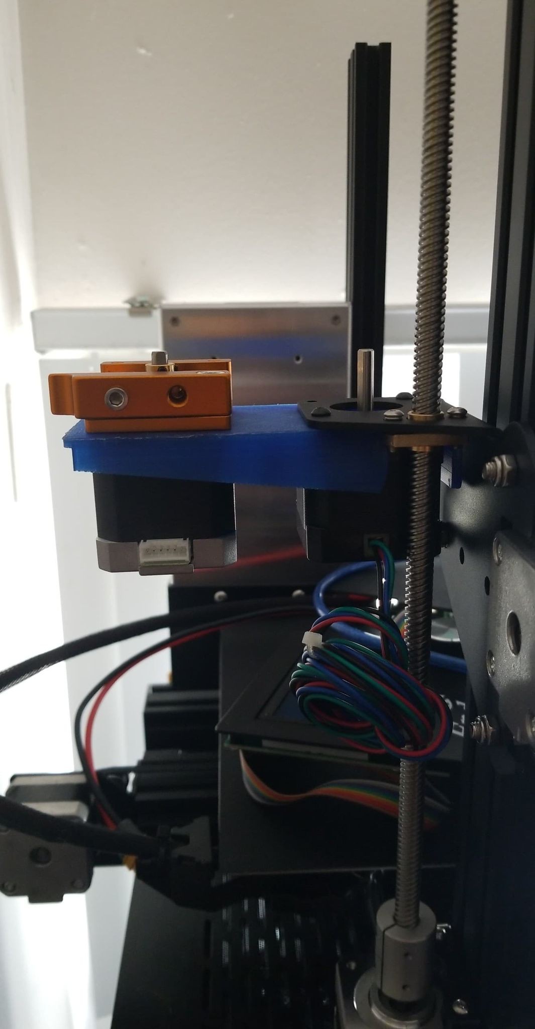
Still having issues with clogging/underextrusion, and just generally needing a lot of force to push filament through, especially after the nozzle has been heated for awhile or both nozzles are heated. I'm pretty sure the root issue is 'heat creep', where the heat breaks get too hot and filament partially melts too high up in throat where it deforms and gets clogged (if you google 'hot end heat creep' or 'heat creep chimera' you'll find a lot of info about why this happens and how to fix it). This is especially pronounced when I try to print PETG in one nozzle, requiring higher temperatures, and PLA in the other nozzle, and basically have to print the PETG at a snail's pace and I actually have to help the PLA extruder by pushing the filament by hand... I've tried getting a 30mm 24V fan that will mount directly on the heatsink (instead of ducting the 40mm fan) and that didn't make any noticeable difference. I then tried mounting a blower fan using a mount from matt448 on thingiverse (https://www.thingiverse.com/thing:1600018/makes) and that definitely seemed to be doing a better job of cooling the heatsink but the nozzles still required an aggressive amount of force to extrude. (but obviously printing PLA out of a single nozzle is mostly fine, since I was able to print the new mount with only a few missed-steps from the extruder stepper)
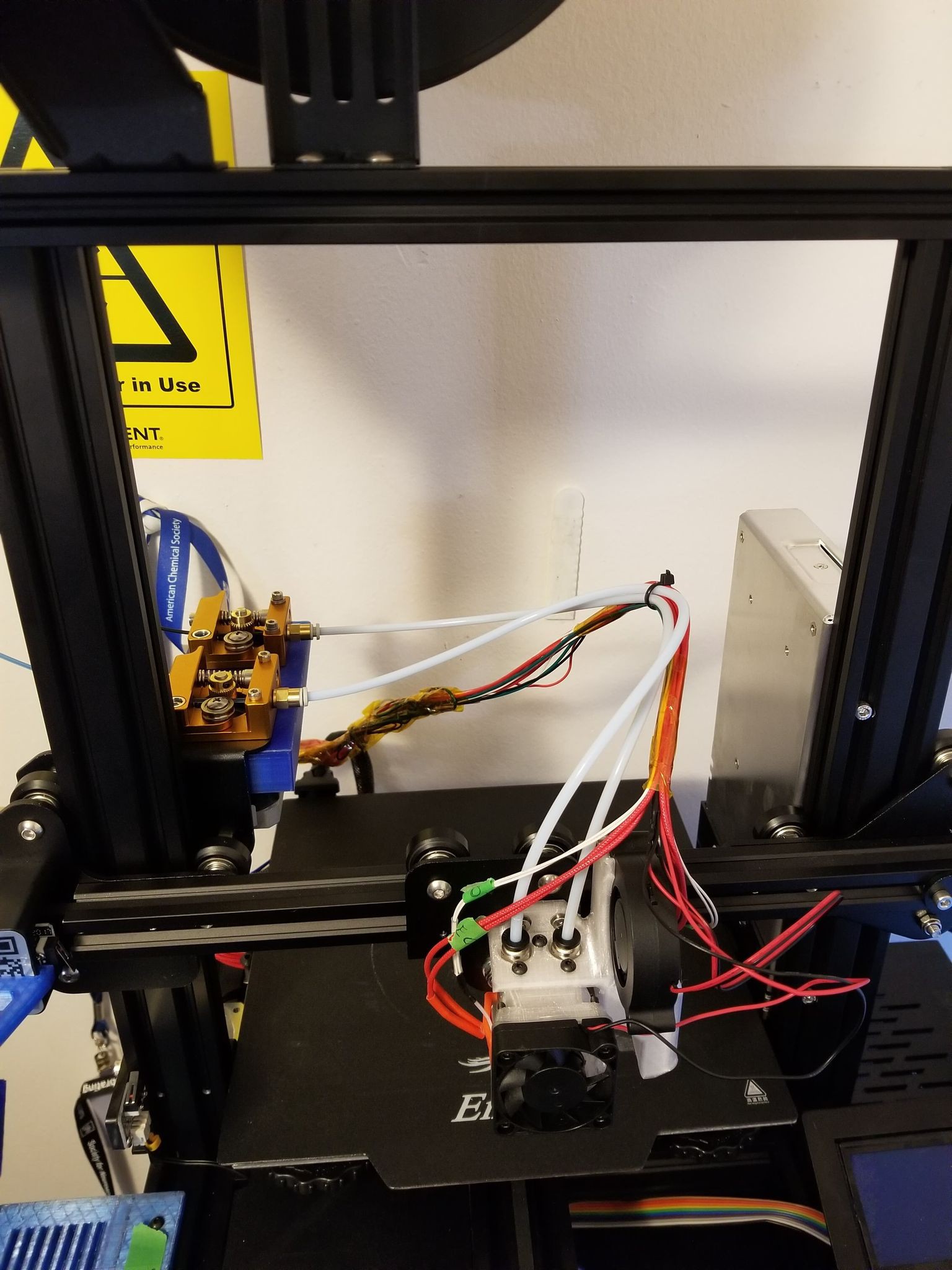
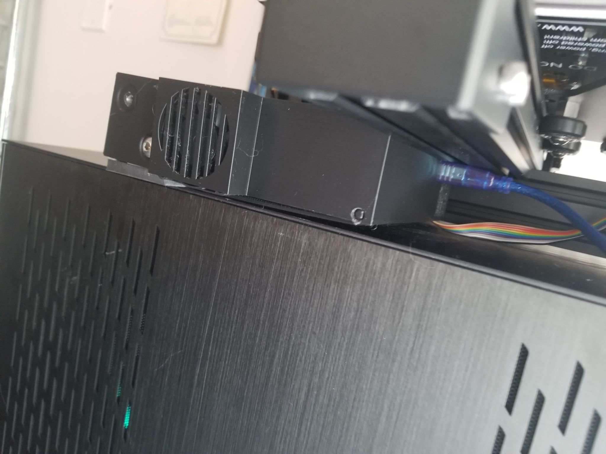
Radial fan mounted on heatsink:
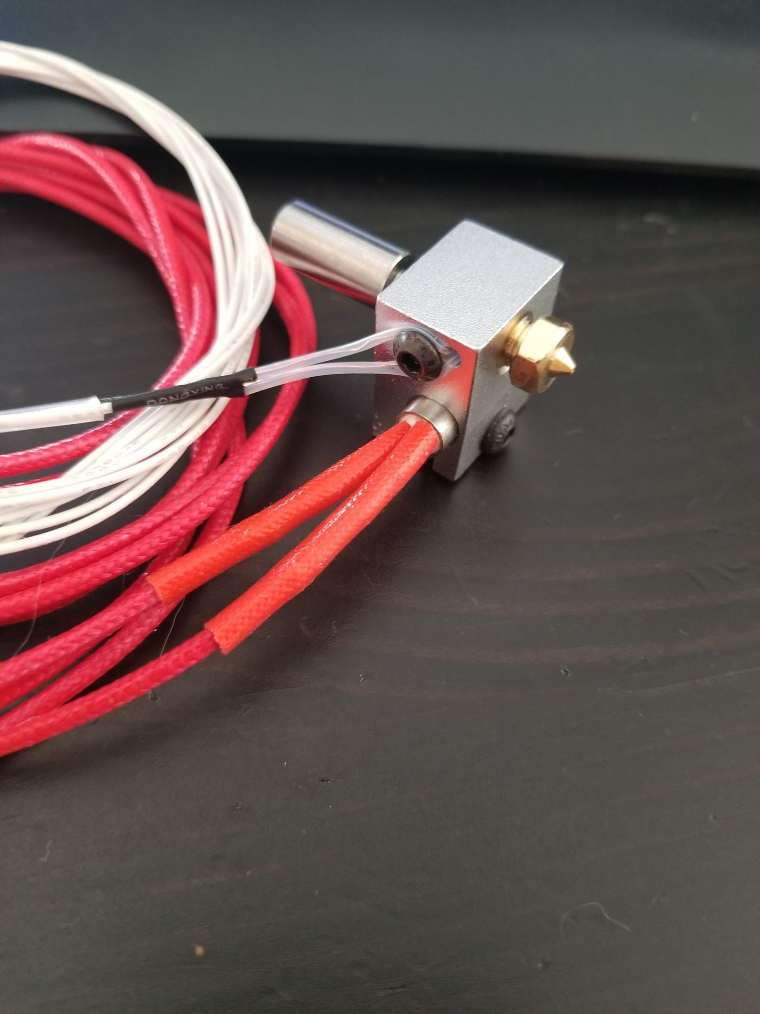
I've tried both the titanium and ptfe lined SS heat breaks that came with the kit and they both have the same issue. I'll probably try out the volcano heatblocks/nozzles that also came with the kit, since those have a larger melt zone and may help to reduce some of the extrusion pressure. I also just went ahead and ordered the legit chimera heatsink and heat breaks which will hopefully...
Read more »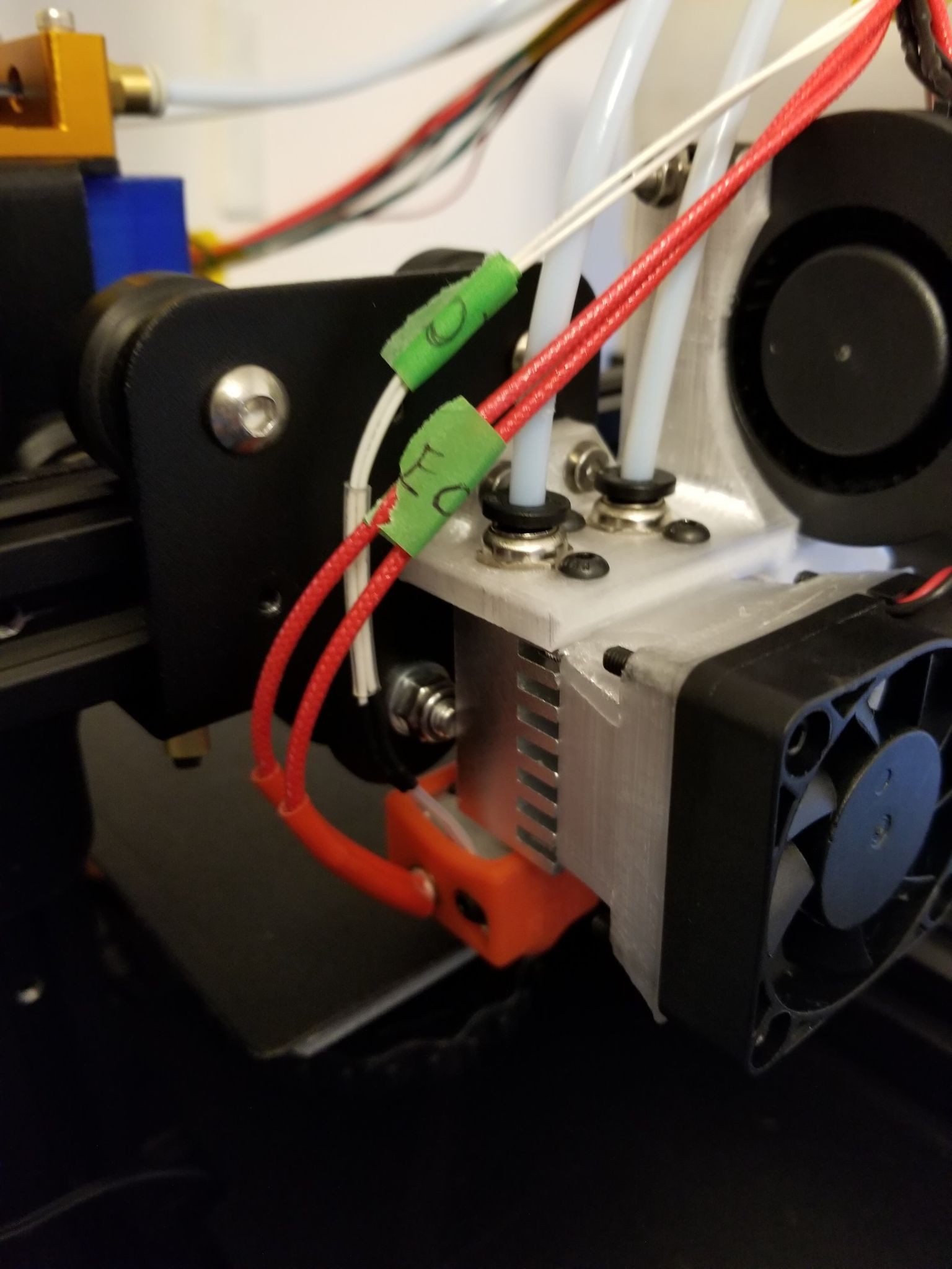
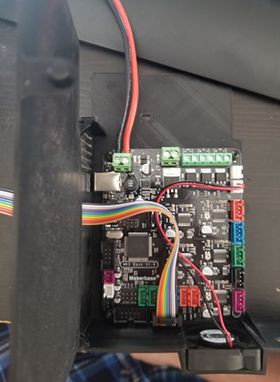
 You'll need a custom printer profile in cura, I just copied the X/Y min/max settings from the Ender 3 Pro profile. There are nozzle offsets you can play with in the extruder tabs, but I haven't messed with those values yet.
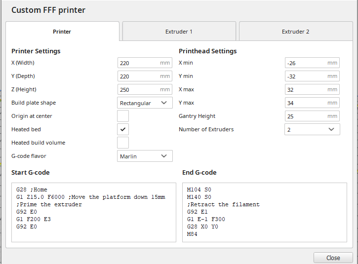

 kelvinA
 Nyles
Nyles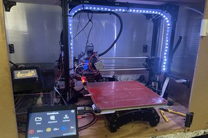
 Dylan Radcliffe