Introduction
One of the biggest issues people report with these ovens is that some parts of their PCBs don't get hot enough to reflow the solder while other parts get so hot they components start to get burnt. In Jerry Walker's video series he adds and small convection fan and concludes this is one of the most beneficial modifications to prevent this issue.
This was, by far, the most difficult modification. It requires adding a motor, a switch, and the fan blade. However, the ideal position for the fan blade is in the center of the heating chamber and there is a thermocouple located there. I chose to relocate both thermocouples to the side of the chamber. This also freed up room above the heating elements to allow the fan blade to be installed between the heating elements and the top of the chamber.
Relocating the Thermocouples
The thermocouples were originally located at the top of the chamber.
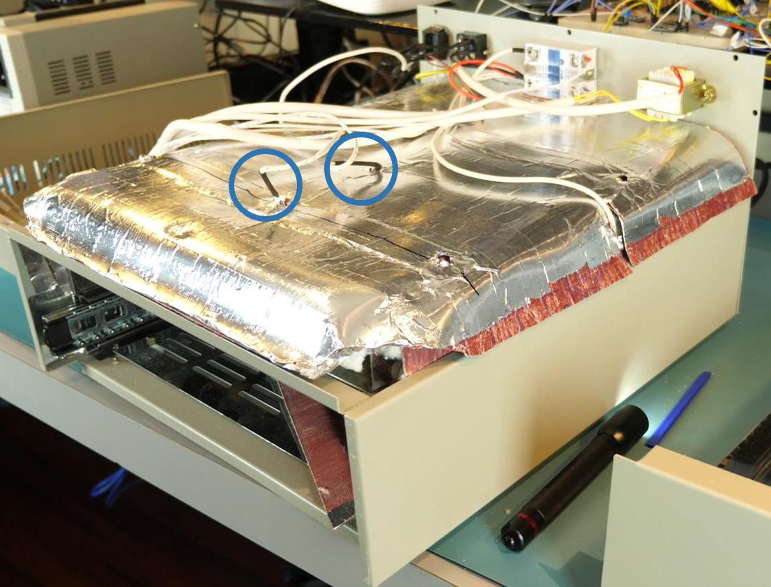
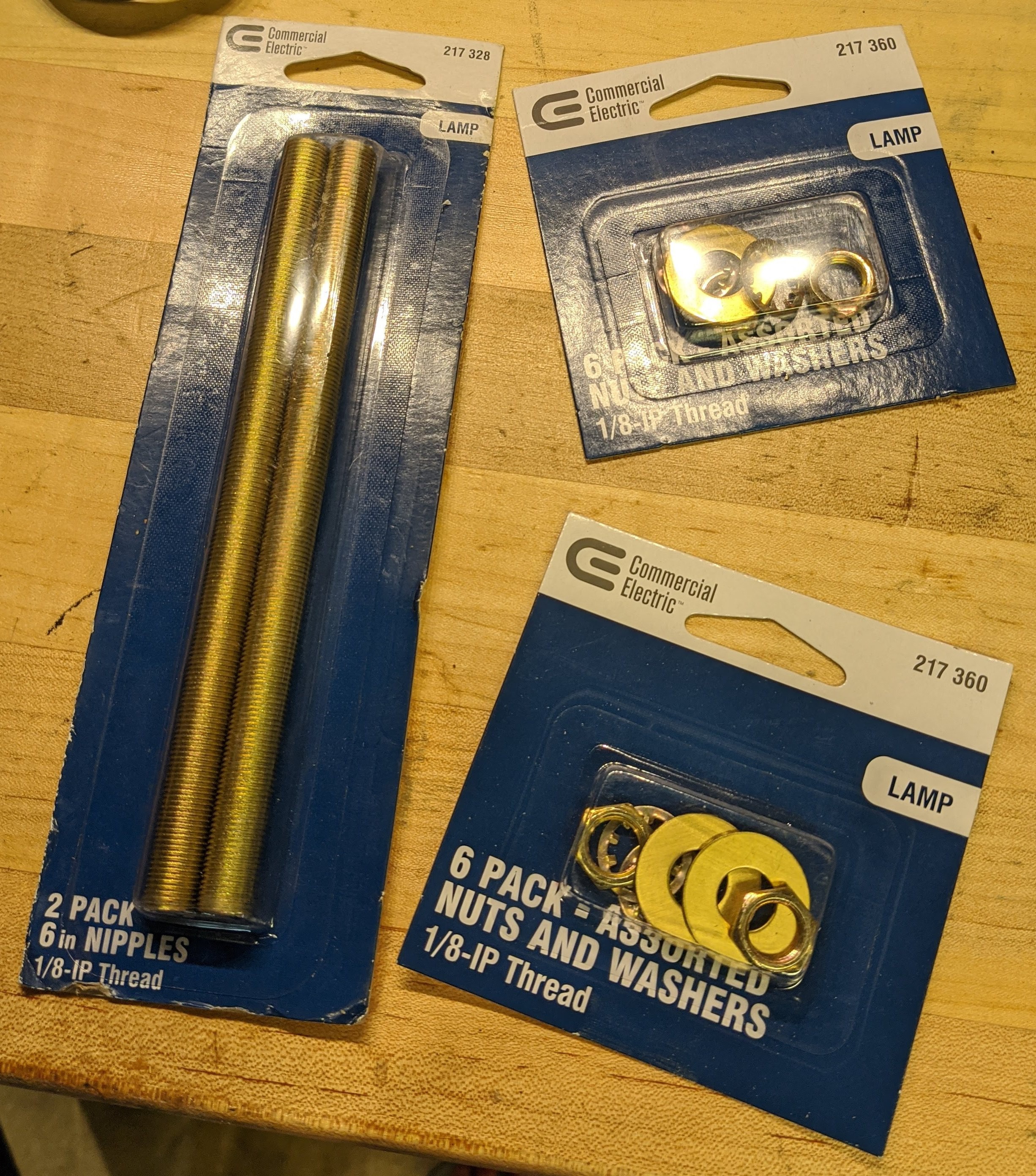
To mount the thermocouples to the side of the chamber, I used some lamp hardware. It is cheap and available at most home centers. The hardware is metal so it will stand up to the heat, the nipples are hollow which allows running the thermocouples through them, and there is nuts and washers for mounting everything.
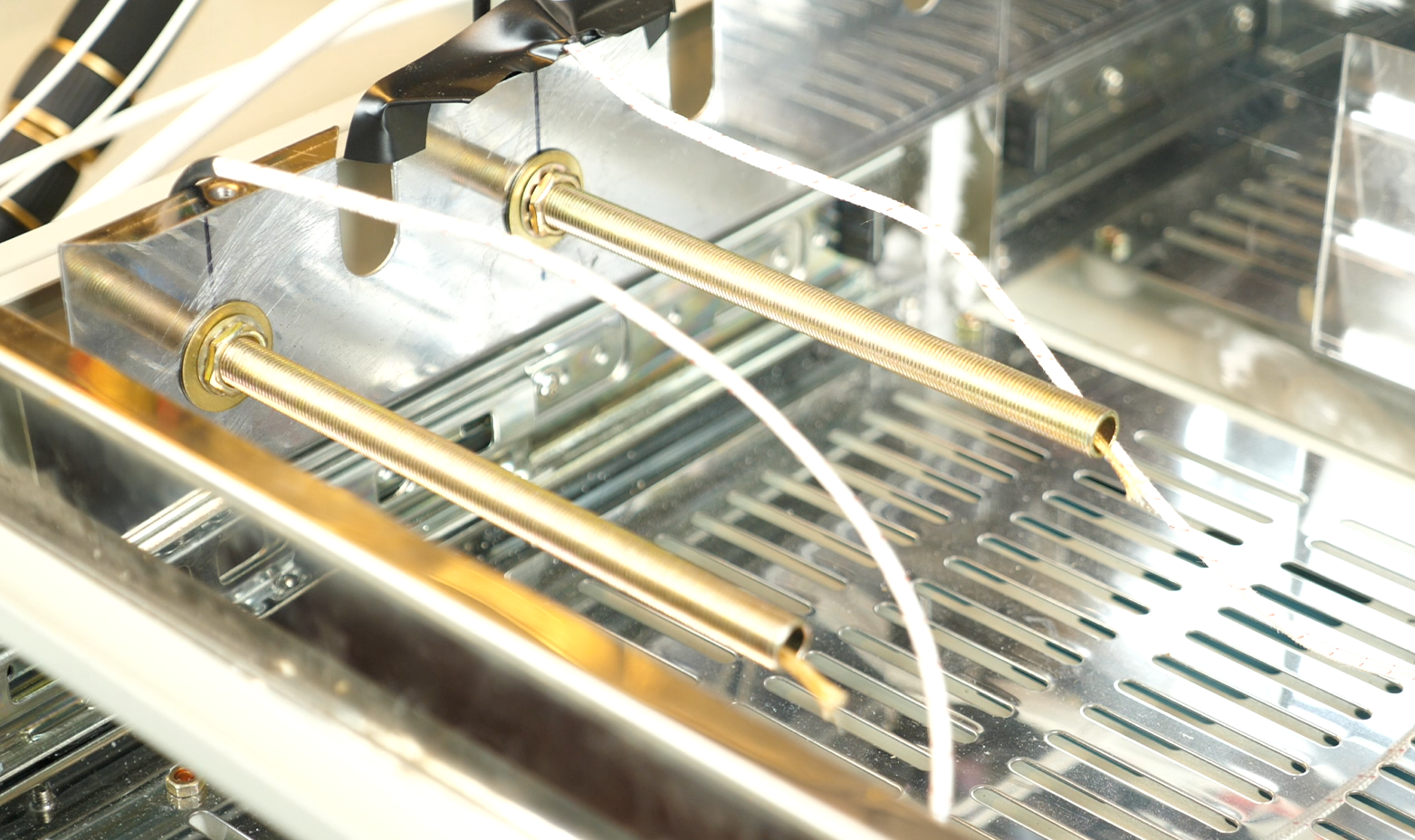
I drilled some holes big enough for the nipples through the side of the chamber. A washer and nut on each side of the chamber wall held them in place. Then it was just a matter of running the thermocouples through and applying some heat-resistant silicone to seal them.
Motor
I chose an N20 hobby motor. It works, but the thing is very noisy. If I was to do this again, I'd definitely look for a quieter motor. A 12v motor was selected so it could run directly off the power available on the control board.
Some standoffs were used to attach a small plate to the top of the heating chamber. A square was cut out of the insulation to allow it to be positioned around the stand. The insulation square that was cut out was then modified to fit between the standoffs and allow the fan driveshaft to pass through. The motor was mounted above the insulation to prevent it from overheating.
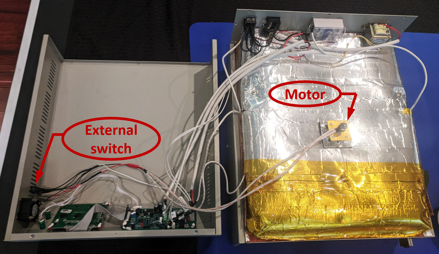
An external switch was added to allow independent control of the convection fan. Heat shielding was used on the wires from the motor. Disconnects were added between the motor and switch to allow service of the oven or motor replacement.
Fan Blades
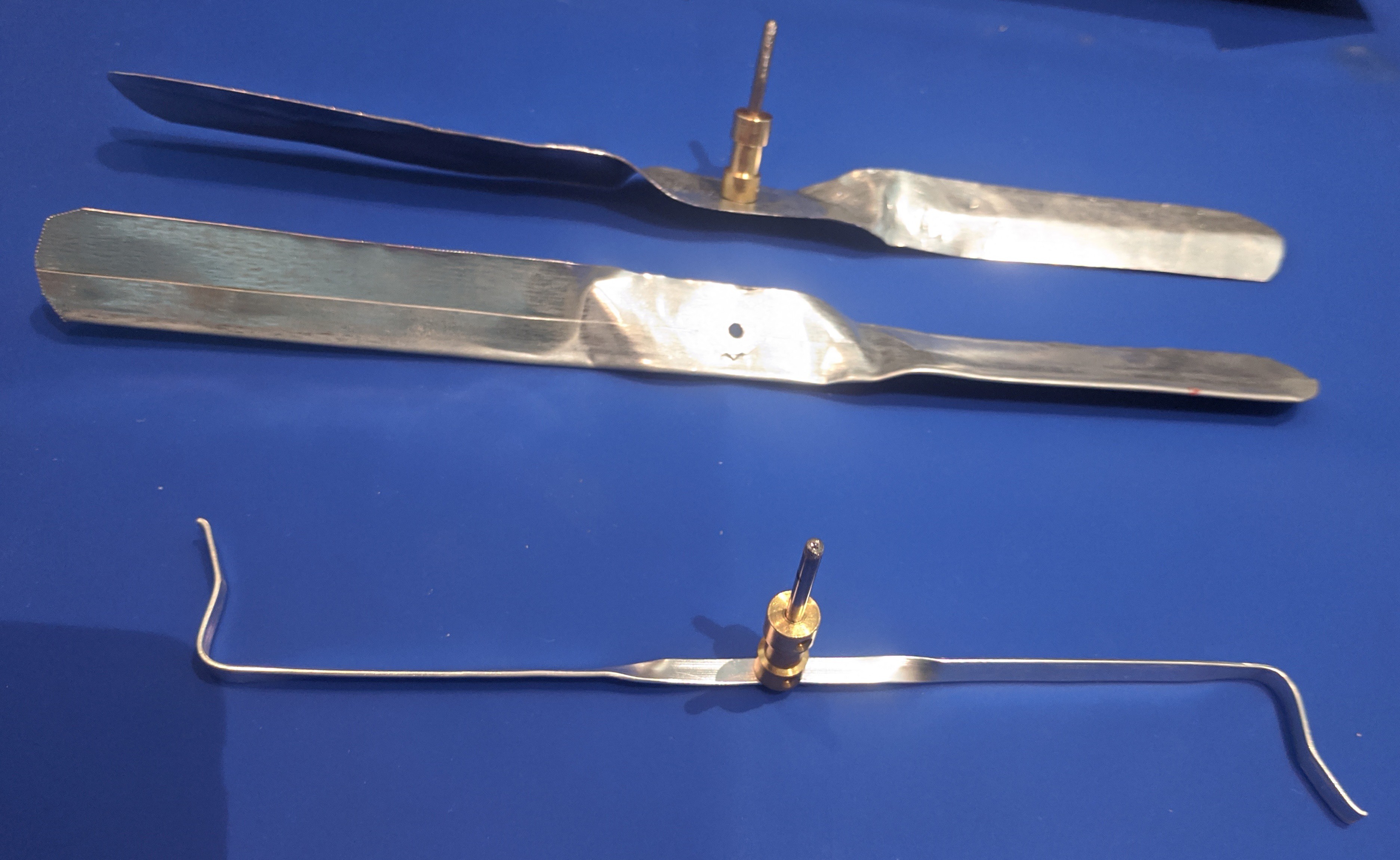
I made two different sizes of fan blades. The first was as close as I could match to the one Jerry Walker created. The second size was much larger. After testing, the larger fan blade led to a large discrepancy between the readings of the thermocouples and what I was reading on a PCB placed in the oven. In the end, I went with the version Jerry Walker used.
 Lance
Lance
Discussions
Become a Hackaday.io Member
Create an account to leave a comment. Already have an account? Log In.