 ridoluc
The PCB design is ready. I tried several options, moving the large components all over the place in the quest of keeping the device as small as possible. It would have been nice to fit more solar panels but two should do the job nicely as anticipated by the breadboard prototype.
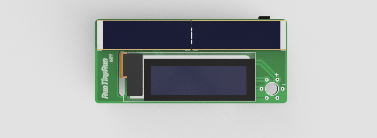
I placed the OLED display and the two IXOLAR panels on one side and all the electronics on the other side.
The OLED connector will pass on the opposite side through a slot.
I placed large plated holes on the solar cells pads. These should facilitate the PV cells soldering.
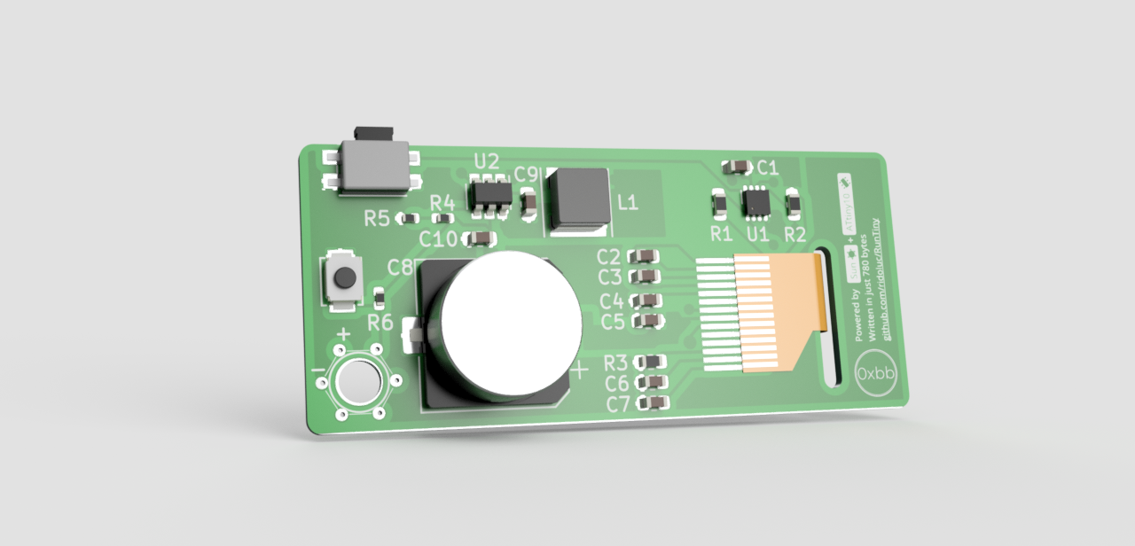
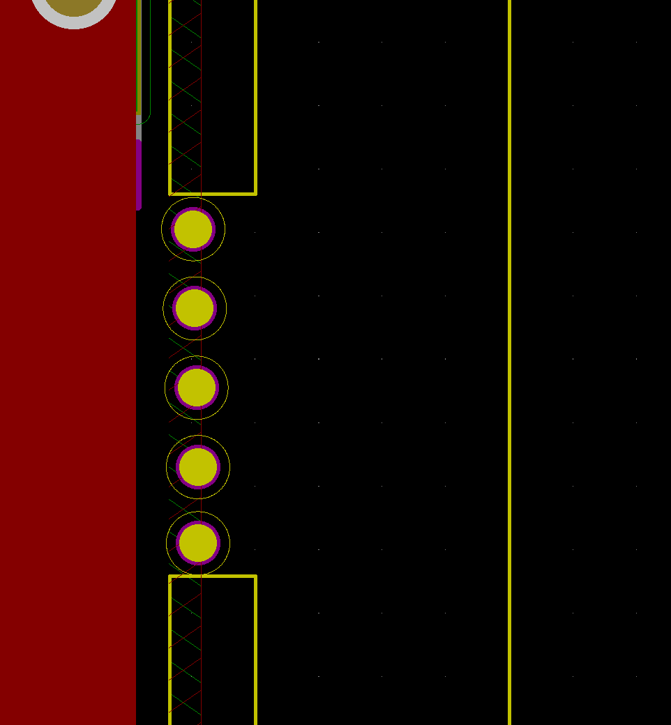
I designed a circular TPI connector for programming the ATtiny10. This has 6 small plated through-holes placed at the vertices of a hexagon. The distance between these holes is 2.54mm so that I can easily build a connector with pogo-pins.
The passive components used are mainly in a 0603 package apart from three resistors that are in 0402. I can't bother soldering these components. I will get the passive components assembled from the manufacturer and I will only solder the ICs, solar cells and the display.
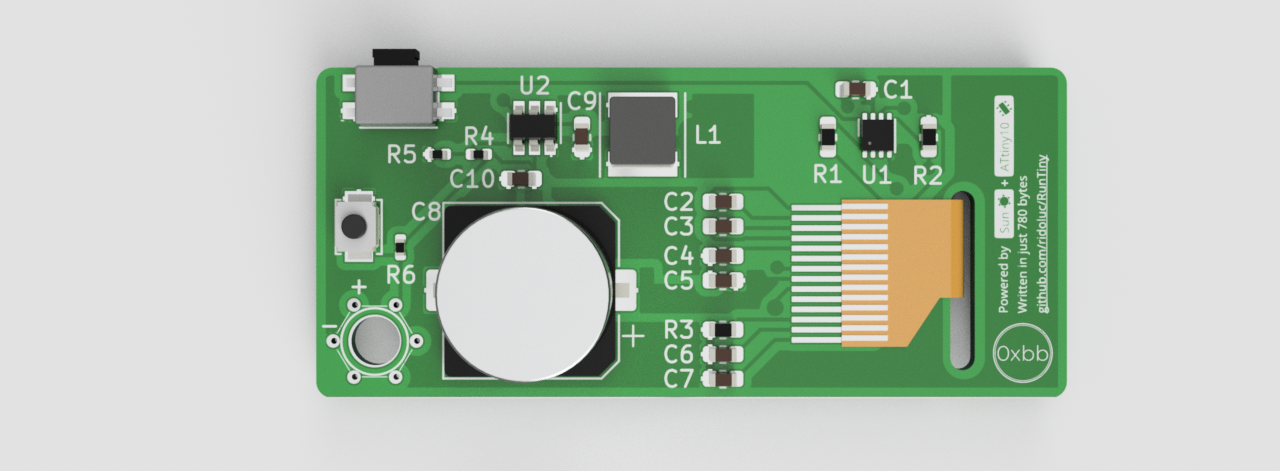
Here it is a few renders from Fusion360 with the model imported from KiCad (I did some models like the display and the solar panels in Fusion360).
Front:
Back:
The manufacturer is going to place two or three tooling holes on the PCB for the assembly process. The holes should have a diameter slightly larger than 1mm and should not be plated. I really didn't want to have these on the board given the small space available. I thought about panelizing the design but after some research, I was still confused about the process to design the actual panel. Also, the board is too small for a v-cut machine.
The solution I found is to create a frame around the PCB and connect this with two handmade mouse-bites. The price will be the same and hopefully it will work as expected.
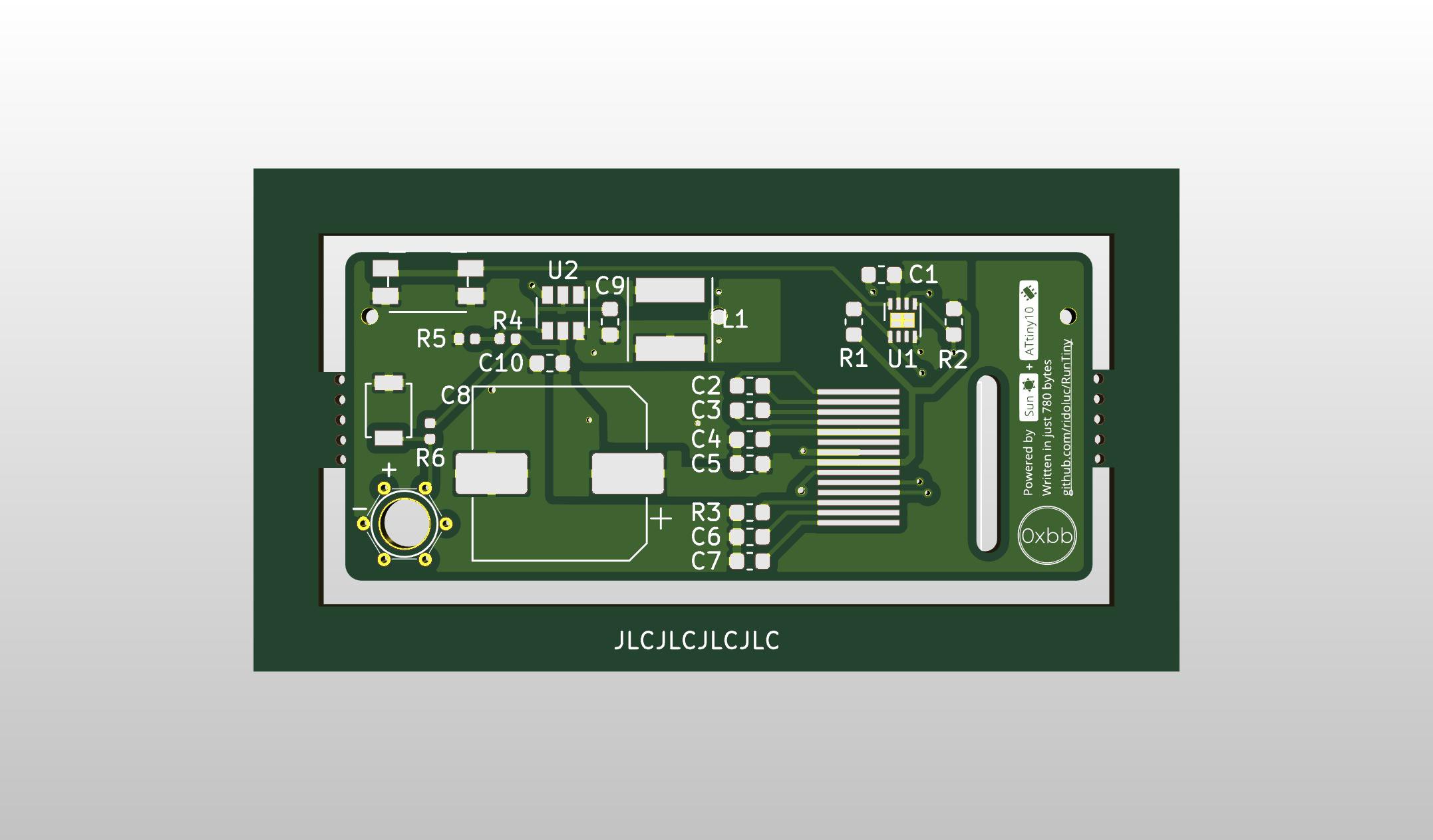
This is very simple to do in KiCad: draw two rectangles around the board on the "Edge.Cut" layer. Then connect the frame to the board with two more lines. To remove the outline on the mouse-bites just right click on the Edge layer and select create corner.
Finally add some non-plated holes. I can't tell the optimal number of the holes or what should be their size.
I have a lots fo doubts about the solutions I'm using. I guess I will find out if this design works and can be improved once I get the boards.
Discussions
Become a Hackaday.io Member
Create an account to leave a comment. Already have an account? Log In.