 Lutetium
Workshop Details:
Those of us using KiCad for circuit board design know how useful the built-in 3D viewer and associated (rudimentary) renderer is. KiCad renderer is getting better, but if you want to get there fast, and want to create some amazing photorealistic renders of your PCB, then Blender's the way to go. Blender can be intimidating to start with, so we'll walk through a couple of simple steps to go from KiCad VRML export to photorealistic Blender renders.
Instructor: Anool Mahidharia
Anool is an Electrical Engineer, who works in the field of Test & Measurement at Lumetronics. He loves to dabble in Astronomy, Origami, Photography, Tinkering, Hacking, and Cycling.
Anool is one of the founders of WyoLum Emergents, a global group of Open Hardware enthusiasts, where he creates original Open Source circuit boards and projects. He is also the co-founder of Makers’ Asylum, one of India’s first community-driven Maker Spaces. He also writes for Hackaday.
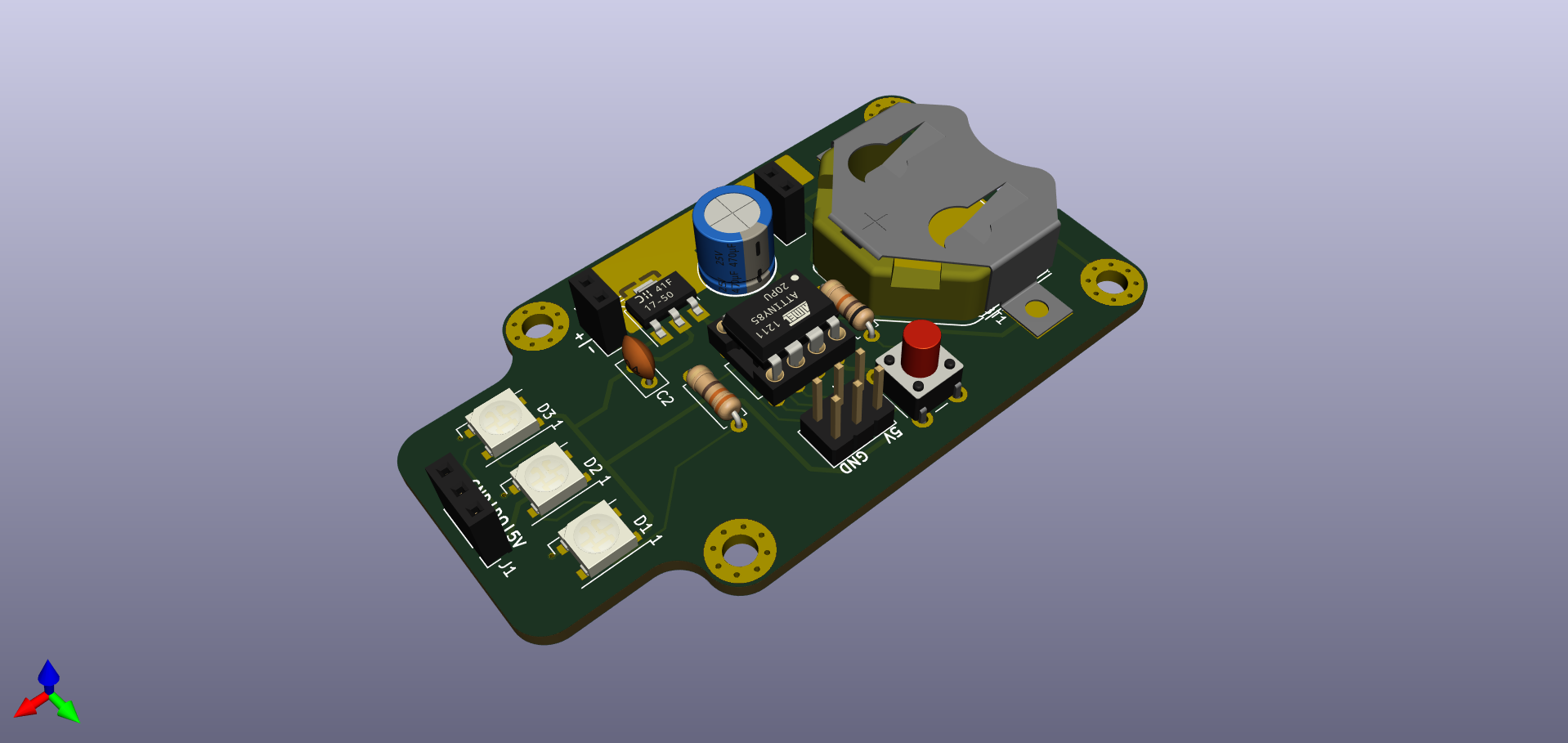
RENDER from KiCAD
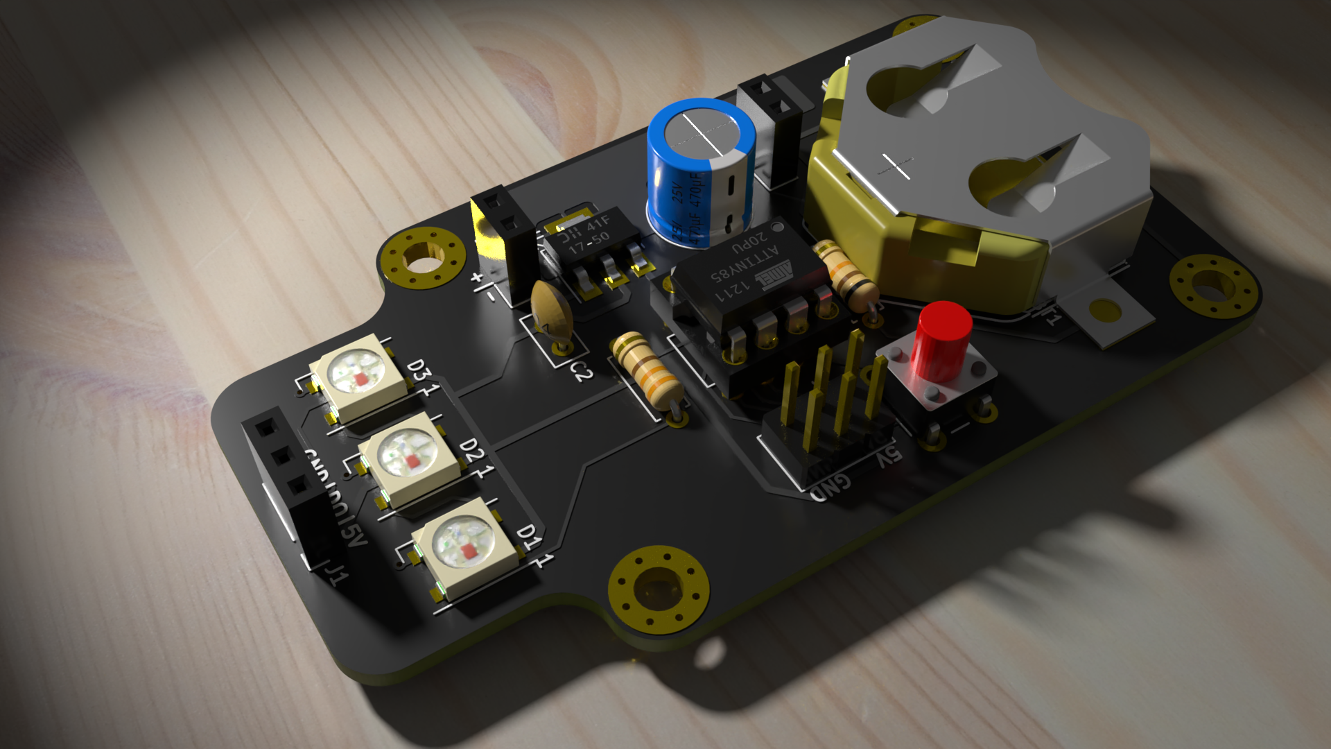
RENDER from Blender 2.83
 nqtronix
 Budi Prakosa a.k.a Iyok
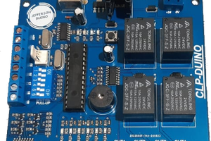
 Jefferson Bueno