Close
0%
0%

Hybrid sensor (Camera + OpenCV, Lidar, Ultrasonic)

This is intended for navigating a slow, indoor robot. It's a proof of concept before the hardware design gets better.

Similar projects worth following
The idea is to take a picture, do some CV magic and then use the "lidar" and ultrasonic sensor to get real physical dimensions at specific points(centroids). Then roughly figure out if the robot(a presumed rectangular box) can get through.

This project has been slow, mostly due to life/interest. The hardware took me a bit to design too sadly(pan tilt) conceptualizing it, it's still trash in the end but yeah. OpenCV is kind of a wall, did not work as I expect. I'm still working on it but that's how it goes with new tech(to me).

At this time (09/29/2020) I have some random bits and pieces of code(mostly scavenged from the web) for the sensors + RPi. I can put the whole thing together but the "brain part" is still in progress as I'm still dealing with cleaning up images/finding the aforementioned centroids.

I'm trying to finish this project though so kind of posting it(despite not being done) for motivation.

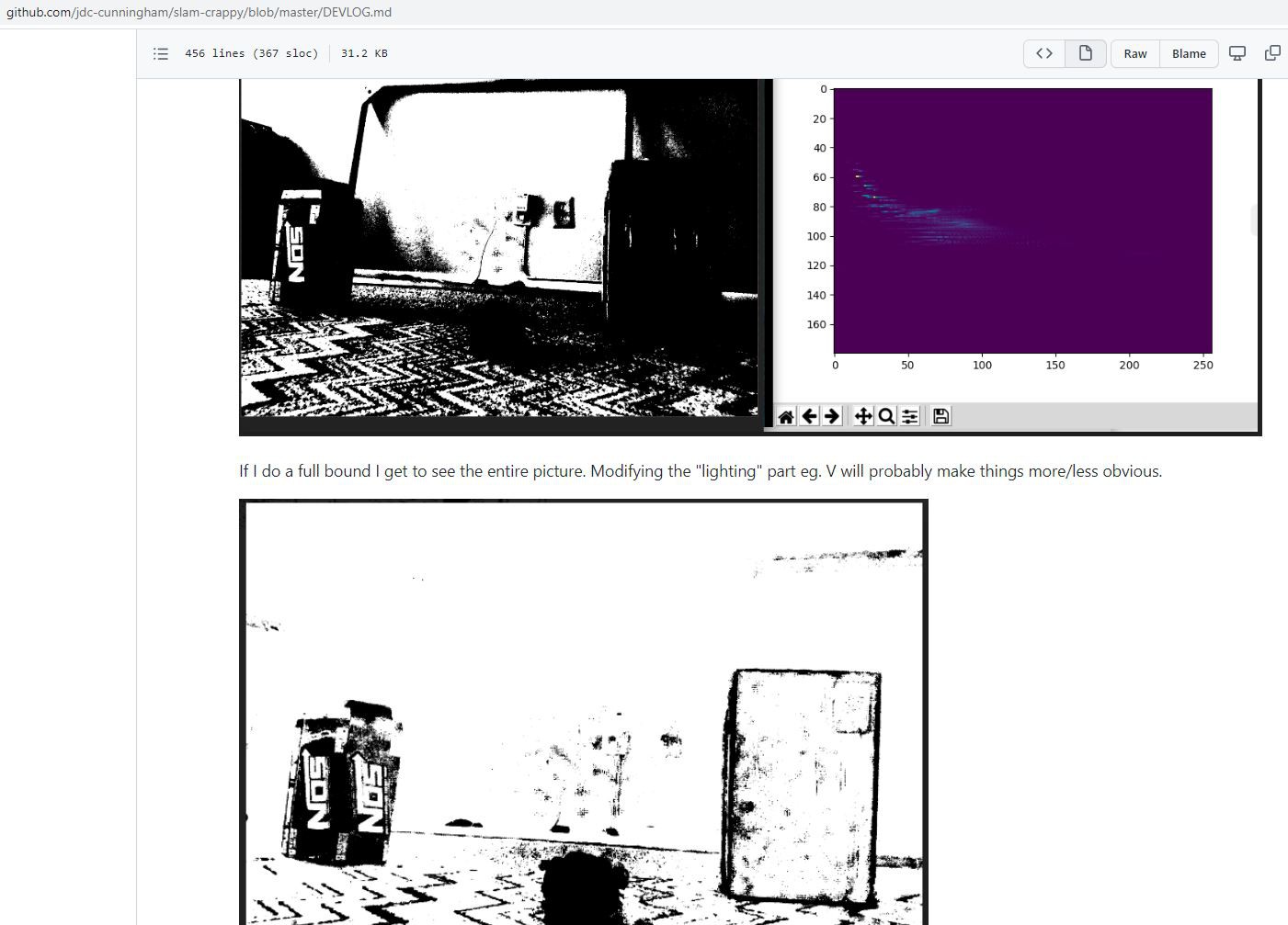
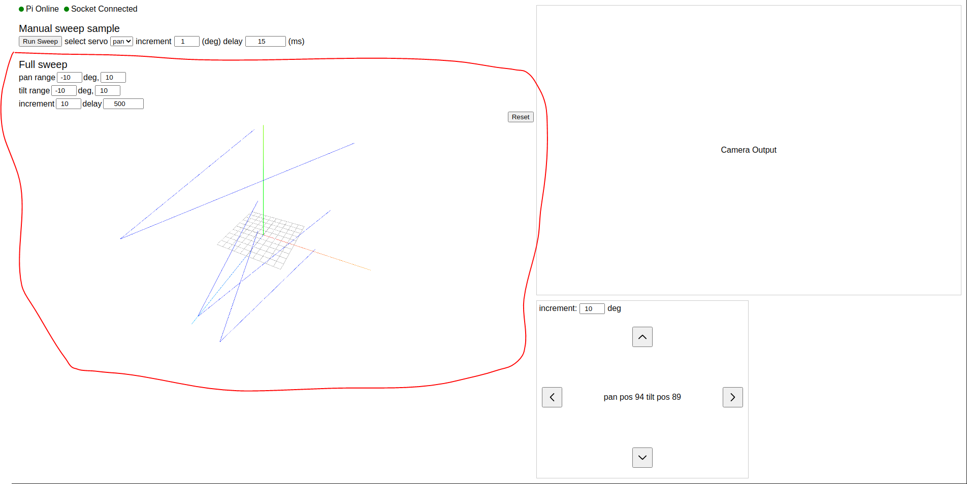
This projected stalled, OpenCV is hard who knew.

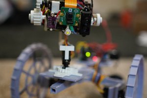
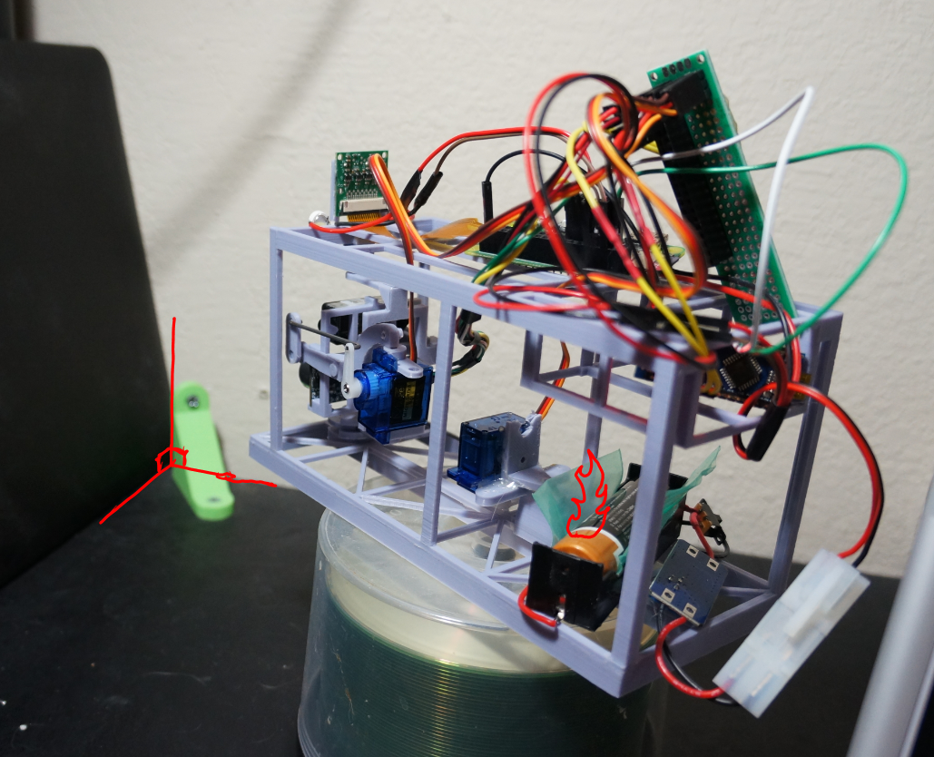
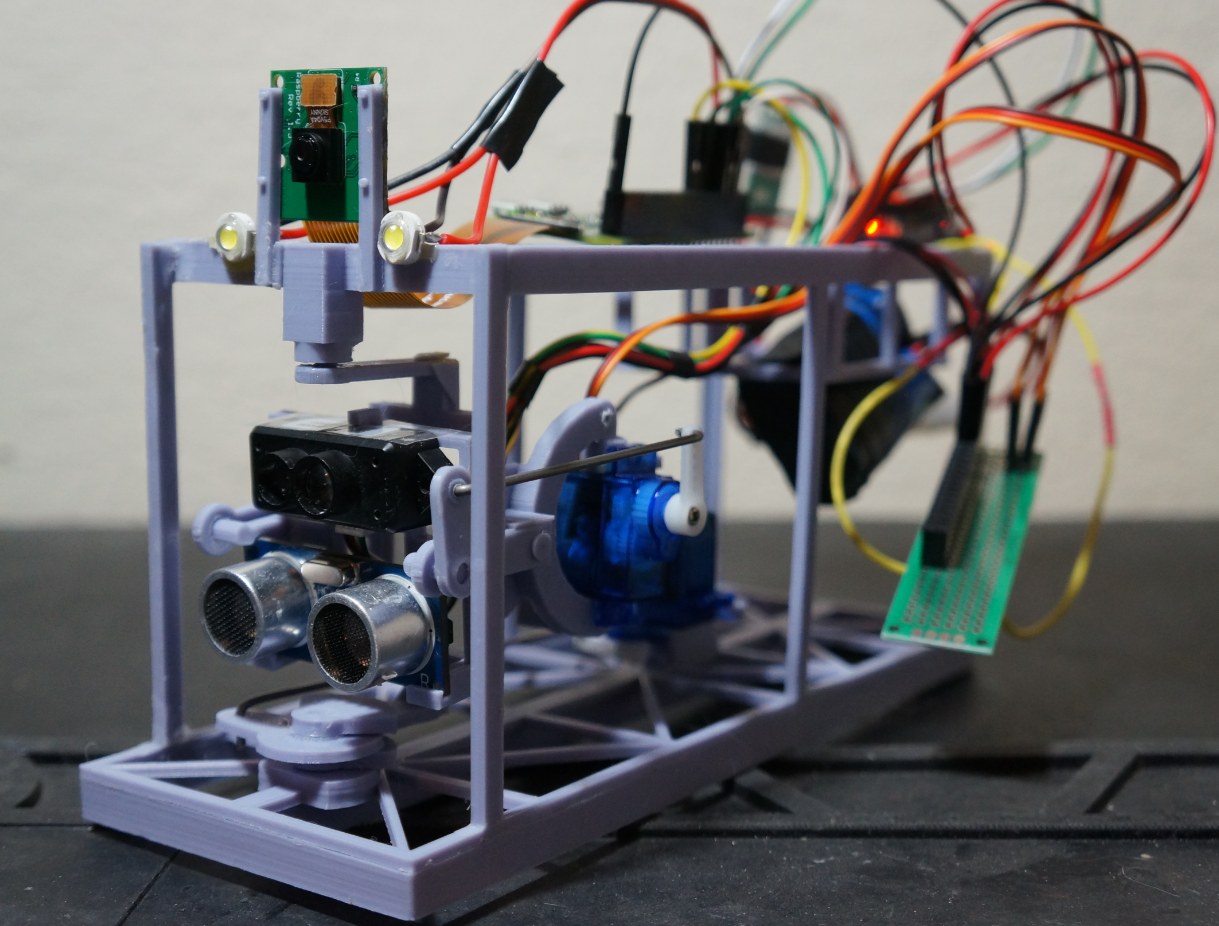
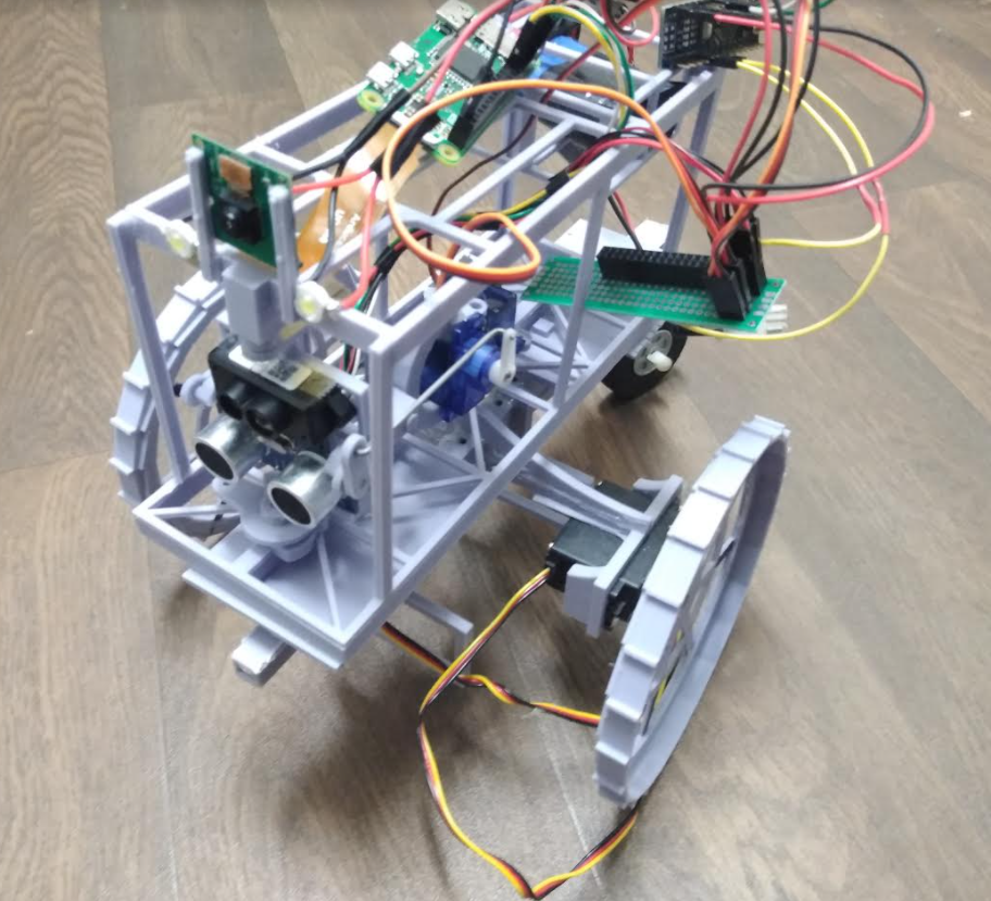
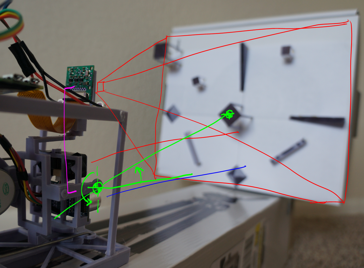
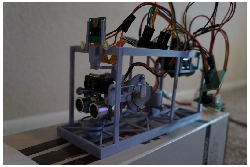
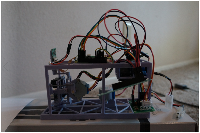
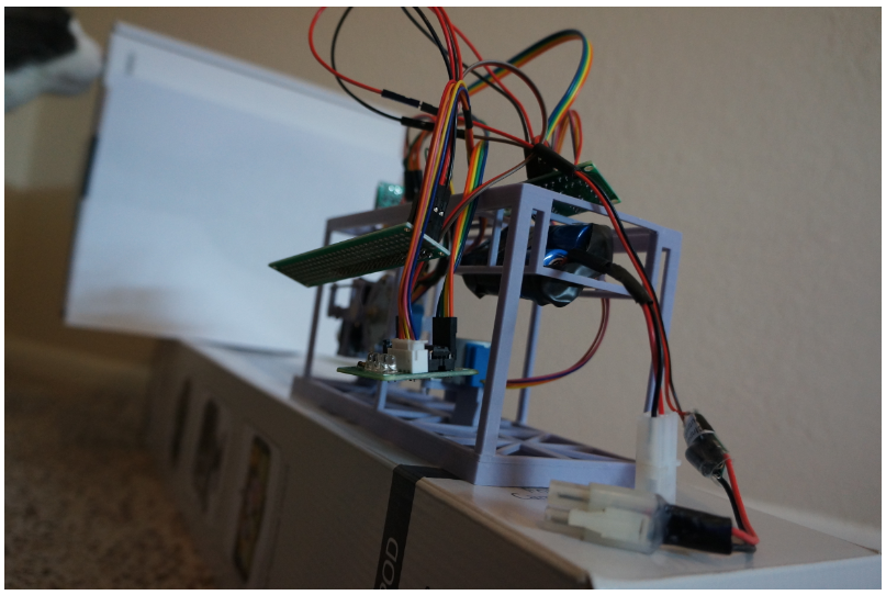
Also the pan/tilt mechanism was kind of a fail due to the stiffness of the wires fighting the servos/preventing them from returning/going to the right position. Also no positional feedback.

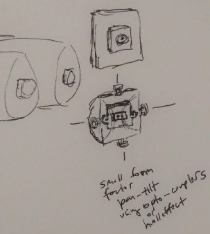
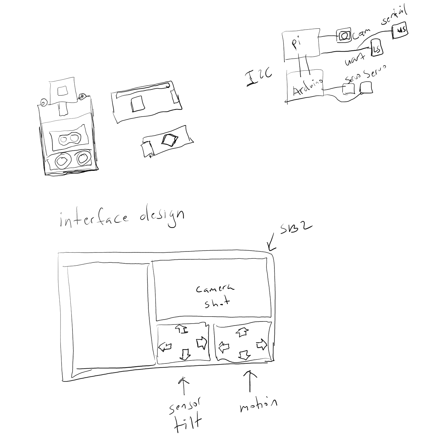
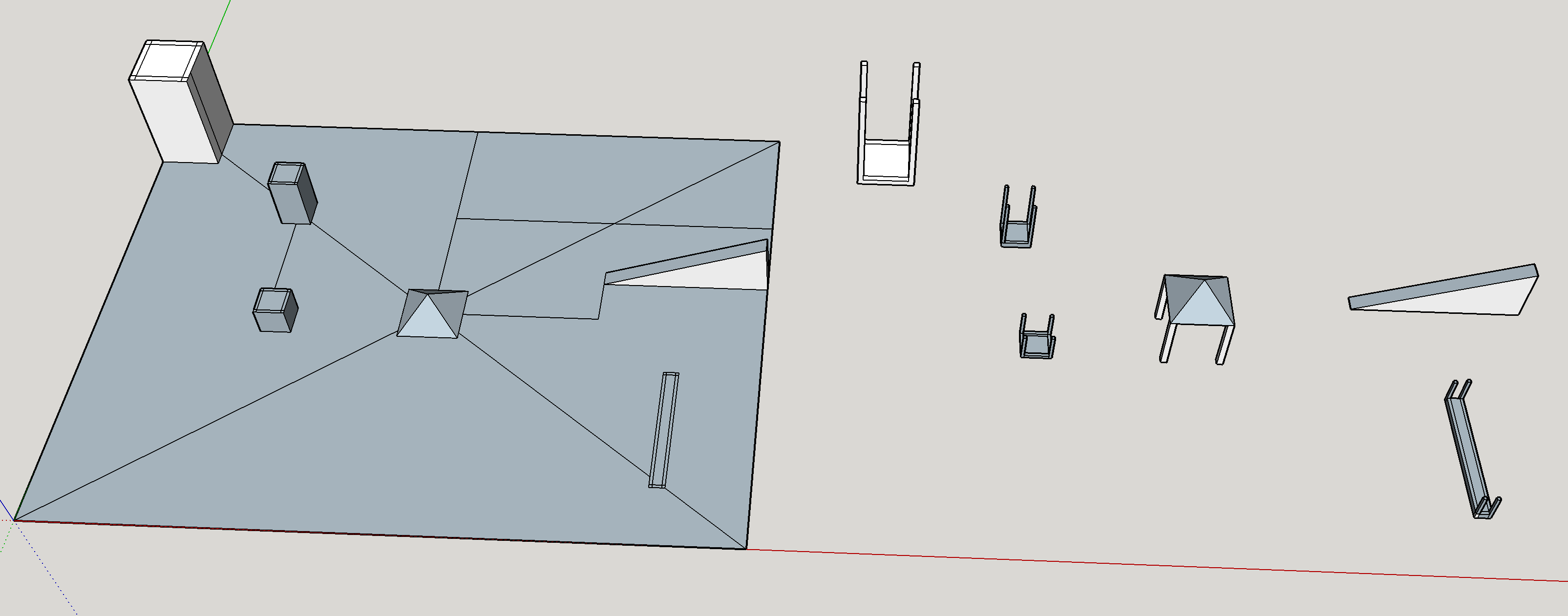
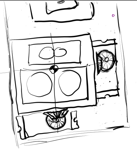
I have another version in mind, smaller like this:

Anyway time will tell, my life might get rough for a bit (transitioning to a new job in the near future).

  • Will return to this project

    Jacob David C Cunningham05/08/2022 at 23:53 0 comments

    This is a late update. I have since changed the github project name to slam-crappy.

    The main flaw with this design is the pan/tilt bed is not accurate due to the stiff wires of the sensors. So a future version I have in mind will use a slip ring/possibly a floating IMU unit (depends on size, channels available) and then that will be more accurate to not get stuck/fight friction.

    The other issue is the method I was using (histogram and light distribution) to isolate objects for bounding. At the time I was thinking it would be an improved way to do the edge detection... but there are other technologies I've become aware of like VIO... which I'm not sure what alogrithm(s) they use to batch pixels together as a blob.

    Anyway I will return to this although not sure when. My Twerk Lidar Robot's navigation system sucks, definitely want to use a combination of vision and Lidar/ToF. Stereo would be cool too.

  • Using single cell battery now, using ThreeJS for visualizing world

    Jacob David C Cunningham11/11/2020 at 20:19 0 comments

    What you're seeing here is the "fusion sensor clu" unit facing a 90-degree wall for calibration/dumb math checks. The default full sweep pan/tilt ranges have a max of 9 samples(3 pan, 3 tilt). I was mostly concerned with the ThreeJS aspect as I was still figuring out how to plot stuff. At this time my coordinate system/math is still wrong since the result plot is not right(looks to represent the beam/measurement vs. actual points).

    The fire on the battery is a minor joke, I had a brief monkey brain moment where I was prying against the battery edges with a scrap piece of 3D printed plastic and I guess I crimped the walls of the battery. It started to smoke/get warm quick... yeah. These battery holders are tight and this is a flat-top type battery cell. Hence I have the plastic in there and that distributes the force/allows me to safely pull the battery out. But I did add a switch so I don't have to pull it out as often.

    This is still far from what it's supposed to do functionally. It's not supposed to be just a "pan/scan everywhere" but using THE POWER OF OPENCV it would know where to aim the sensors and roughly where to measure.

    The ThreeJS aspect took me a bit but was far simpler than raw WebGL which is what I was initially going with. The ThreeJS is just a nice visual thing but ultimately all of the "computation crunching" will happen in the background/in loving memory of Python.

    I'm not a spatial/math whiz guy so it will be a struggle.


    This is the update to the UI so you can see the "full sweep" settings and then the resulting threejs render below. The lines is just me testing/confirming the trig math for coordinates but it will actually plot the robot  box itself vs. the world's measured polygon positions.

    This thing is real hacky... there's no real time feedback from the servo position so I can't tell if they're done moving. I'm just banking on the general delays/half-delay pauses while sampling. For the most part it's okay. I will have to rework this stuff though, to be more robust mechanically and use a single board if possible eg. something like a Beaglebone. I would try to centralize everything eg. use Python for everything so I can use threads/not having to hack some NodeJS socket to Python to Arduino communication stack.

    Video of it working, sorry it's not prepared, I don't really have a studio. No dedicated mic, I was crouching on the floor.

    I'll beef up the ThreeJS stuff next, will confirm coordinates plotter right with some more UI toggles. Will try to get actual solid polygons plotted. The "hard/future" work would be updating meshes so if a box is not really a box/assumed angles are wrong can update it.

  • Switched to servos and now using Pi Zero + Arduino Nano

    Jacob David C Cunningham10/28/2020 at 09:44 0 comments

    So... the steppers were not a good idea after all, went with servos. Also after seeing the servos almost strip themselves on boot and move randomly(directly connected by GPIO no pull down/driver) I went with an Arduino. Thankfully after following some tutorials I got the I2C to work and it is clean! It's not like that jank software serial I used in the first legged robot I made where I can't even guarantee a single character will arrive correctly.

    Anyway I made the interface below, it's pretty sparse in features but man! I made it, the "whole stack" from the web interface down to the servo. It's hacky my methods for sure. I used ReactJS for the interface, node for the socket server and used a system call to execute a python script with cli args for the servo details then Arduino picks that up by I2C to move the servos. This interface is mostly for manual calibration/testing. In the end OpenCV will drive the whole thing/even the wheels.

    This I2C communication is so crisp, the software serial I used before was awful granted that was between an ESP8266-01 and the Nano... but it looks like you can setup the EPS as a master to the Pi for I2C. I had problems with hardware serial on the Nano at the time.

    This web interface isn't much so far but the little status lights are cool because they're actually from the Pi responding.

    I had some major problems with the simple I2C wire byte read to string and trying to concat/parse the commands for the servo/position... I found some way to make it work but was not how I was initially going to write it.

    There's a repo now, has the functionality in the video

    https://github.com/jdc-cunningham/sensor-fusion-clu

    It would be hard for me now but I just have these thoughts like for example the pan/tilt system, say it was big enough/or components were small enough that you could run it "isolated" or "free floating". The bearings/joints would be how you conduct power through but the stuff happens in the floating gimballed unit. And it would have an IMU so you could really know that the plane of the sensor board is flat(vertical/pan zeroed). I know... overkill, just put hall sensors on the axes or don't even bother... just barrage it with a bunch of data/training/lots of images.

    The other thought for the Lidar since it's single point either do some kind of "phased-array" thing(look at me I can read) or idk... like a spinning "diamond facet" thing that goes towards the beam and reflects in different directions... that's hard. I don't know... I'm burnt, pulling stuff from nothing.

    I am getting more and more driven to make significant progress on this, now it's like in one piece and the basic "control systems" are in place to expand on.

    Slip ring is what this thing could use, have most of the sensors eg. ToF sensors/IMU/Aurduino/battery in the gimballed section then transmit the data(minimum I think would be 4-5(I2C wires(3) and power)). Then you'd have this theoretically low-friction thing that has no bias to turn either way due to the drag from the ToF sensor wires.

    In the end this is what will be moving around. I still have to interface with an IMU for the first time, that'll be interesting. I've watched some videos in the past(about the integration/drift and what not).

    I realize you could use one of those Jetson things and just train something... run it off camera but the problem is that's not always guaranteed to work... I want something that actually knows physically how big it is/where it is... so this project also involves 3D collision map checking... it would be cool to eventually reach you know a 3D simulation plot/real time telemetry output.

    But I am aware the Pi Zero kind of sucks  computation-wise although I like its size.

    Bonus

    This is a robot I designed like 8 years ago or more. At that time I was not into software/could not build a robot if I wanted to. I was into model airplanes...

    Read more »

  • More stuff, no new code yet

    Jacob David C Cunningham10/16/2020 at 21:35 0 comments

    So I printed those parts out, and then I folded a standard 8.5" x 11" piece of printer pay in both x/y (or is it z) axes. Drew lines, these are obvious references. Generally I mounted stuff against these lines. I didn't really measure(I was supposed to but lazy). I have a rough idea though based on the paper dimension.

    I glued them on, I know the part dimensions since I made them in Google SketchUp(CAD program). I set the "unit" back a certain distance(I put some basic markers eg. 6" away(too close), 1' away(usable) and 16" away.

    I'll go over some concept ideas of what I intend to do, these steppers have a terrible slop in the gears. I'm talking 3-5" of swivel between the gear slop and linkage slop...

    One main thing I don't know right now is how to guess how far away something is as a starting point. I mean when you look at something, if something is huge you would think "that's close to me" but it could be massive and be far away.... small and still be massive and far away...

    But... this is generally intended to be indoors and I can do some preliminary bounding/scanning as a combination from CV and physical distance measurements(LIDAR sweep).

    Gahh "golden rule" come in handy right about now regarding mixing sig figs/errors.

    edit: this green part may not make sense, I'll probably have to elevate the base up so when the sensors are level, will be the "center" of the rhombus thing.

    Some major goals are being able to do the shape finding/contour/area/blob/etc... with OpenCV then also labeling(text tagging on image by coordinate). I'd like that so easier to know what's up with an image. From that can do the sizing/pixel measurements and determine angles to move on the stepper, etc...

    Also I want a GUI, desktop preferrably so will probably try and build something with a C++ graphics library(maybe wxWidget). This UI would be for the calibration/seeing an interactive program in real time vs. having to write code(after the code exists). This is pretty ambitious since I don't really use C++/that low level of stuff, browser-based sure no problem... I'm trying to avoid going that route but will see. Would like to put down some time to learn C++ in a real application.

    I also have to figure out some way to mock the pan/tilt/stepper motors because it's annoying trying to code by SSH on the Pi(nano), so slow. Also slow to code by Filezilla/direct edit.

    The dimensions will be related, so there will be a "center sensors" function that will look at the calibration guide above(raised platforms) and it will center against the middle rhombus thing. It's all rough dimensions... then will have max arc-sweep and track position... will be loss/drift/etc...

    Cat tax heh

  • Printed top layer, in one piece now

    Jacob David C Cunningham10/13/2020 at 00:01 0 comments

    I have lost interest in this thing... the desire is still there for 3D mapping but I am still very much an OpenCV noob. This method is probably dumb/bad. Still I like the idea of "real dimensions" vs. estimated/assumed from say stereoscopy. Granted I am not  expert in any of these fields... just bs.

    Right now I'm printing some shapes with known heights. I made this basic L-shaped thing so I had a base/platform to mount those raised shapes/angles on. Then the distance sensors will calibrate against it. I'll give myself a handout by making the shapes have a black surface(Sharpie) so it sticks out against the white paper background.

    I'm super beat today so I can't really think anymore, just wanted to post something. I'm actually trying to push this project aside, while making some notable progress(like the calibration GUI written in something that's not web-based or a web-wrapper). That's a learning thing, give myself false sense of value on the market.

    The other project is a true 4-legged robot with 12 servos. I saw some videos on YouTube showing it's possible to get decent movement with the cheap 9g servos and 4 legs... this time I'm using one of those 18650 cells on purpose with a boost converter. Plan is to use a sweeping ultrasonic sensor for navigation. I also got a little BLE module I've never used one before it looks pretty cool/simple of a device(4 pins).

    I could have switched these to servos but honestly done with it. Will spend more time on the code than the build... the top piece since the thing is solid(battery area is not glued) it took 7 hours to print that... the front-most vertical supports are extra... also the camera mount is backwards and not tall enough(ribbon cable).

  • Current state

    Jacob David C Cunningham09/29/2020 at 23:47 0 comments

    I realize this probably has major flaws, something that is 10ft away vs. 5ft away will have different measurements anglewise, so idk... it might be a very dumb design/idea guess I'll find out at my own expense. I am aware spinning ones exist that give you a nice real time shape of the surroundings, at least in a 2D plane, this is not going to be fast. As mentioned the computation is the Pi Zero which is laughable, will probably use a remote computer(full sized Pi on same network).

    Anyway it's mostly an excuse for me to learn OpenCV and then also to give my robots a brain since they just run into stuff.

    "center of the centroid"

    I intended to have these bumpers like how 3D printers "zero" themselves. But I'm not going to invest much more time into this thing since it's a bad design to begin with. I'm just going to work on getting a thing that's in one piece, can control two continuous-rotation servos(wheeled robot) and I'll calibrate it with a printed board/surface with known heights/distances. The camera will face that irregular platform and find the centers of those and calibrate, will use easy colors eg. red/green/blue.

    Edit:

    One problem/consideration is to use two "computers" or is it one and then a microcontroller. I liked the Arduino for things to do with servos and also the analog aspect(no need for ADC on Pi) but the issue is the communication between the two things(by serial). I had problems with hardware serial on the Elegoo Arduino Nano. The "brain" or RPi would do the calculations and then send that info to the Arduino which would then control the lidar servos for pan/tilt and the robot(servos/wheels).

    I also thought about how to have the Servos directly mounted to the axis and not take up significantly more room using bevel gears and direct mounting.

    Ehh it still looks bad/takes up too much room

View all 6 project logs

Enjoy this project?

Share

Discussions

Similar Projects

Does this project spark your interest?

Become a member to follow this project and never miss any updates