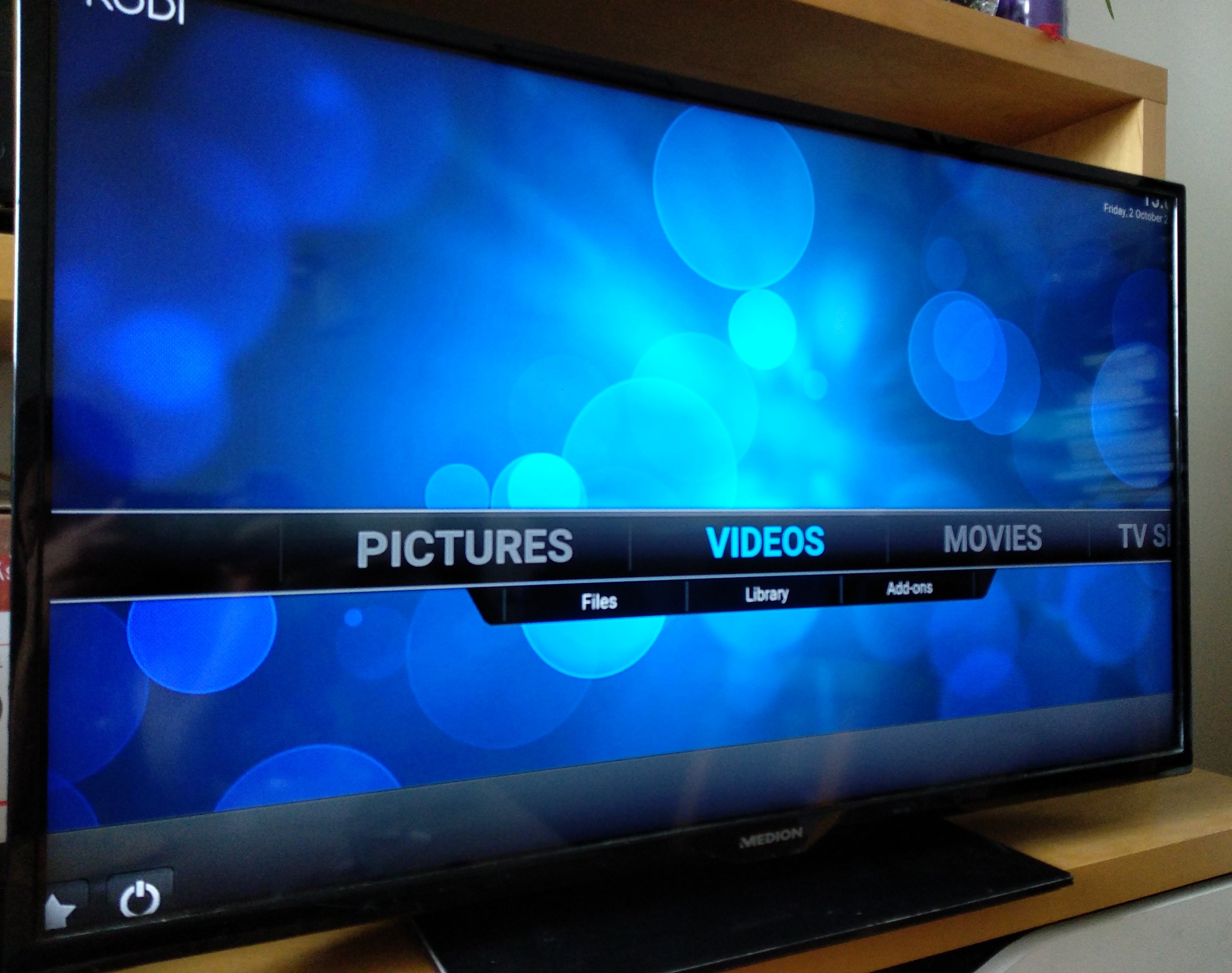
• Conclusion

    benjaminaigner10/02/2020 at 19:04 0 comments

    I think this problem could have been easily avoided by the manufacturer.

    The PCB was mounted tightly by 4 screws to the flexible metal backplate of the TV's screen.

    In my opinion this led to hairline cracks in the solder joint of this PCB.
    Possible solution: use plastic PCB spacers which allows a little movement of the PCB.

    Describing this project on HaD is also some kind of self-cleansing ritual. Repairing this TV was not easy and took me a lot of spare time.
    It is really pissing me off: there is a 5 year old TV which is perfectly fine for my use-case (I want to remove the tuner anyway), but it broke down because of wear down issues. Still, the lack of information and possibility to modify devices nearly led to another ~5kg of e-waste. If the sources would be available, disabling the tuner could be done in no time.

    I find it funny, that you can repair some of your gadget with your kitchen oven. Maybe it was pure luck that this method worked 2 out of 2 times.

    In the end, I am enjoying a bigger TV (upgraded from 32"), a friend of mine got the 32" TV. 
    I learned a lot, got a free TV and saved some resources by avoiding e-waste.

  • Oh yeah, PCB cookies!

    benjaminaigner10/02/2020 at 18:56 0 comments

    I did this procedure once with a graphics card (Radeon HD 7870 GHz Edition), which had the strange error of supporting only EFI/BIOS resolution, even the boot screens of Windows/Linux crashed the GPU.

    It works until now without any problems (~6 months of heavy Corona-caused gaming usage).

    I do not have a clear procedure for doing that, but it takes roughly these steps:

    • Prepare the PCB: remove all components which are mounted after the original solder procedure.
    • If the PCB has SMD parts on the bottom side, use spacers: every part should not touch any surroundings! In case of the graphics card, I used Makerbeam profiles with M3 screws. The TV's PCB has nothing on the bottom side, so I just placed it on the grate.
    • I am not sure if it is helpful: maybe cover regions with aluminium foil. These regions might be parts you know the are working correctly or plastic parts you cannot remove
    • Put the PCB into the oven (I put it in the cold oven)
    • Preheat to 150°C.
    • Wait for the oven to reach the temperature, and wait for a few extra minutes (2-3min)
    • Heat up to 175°C, wait another 2-3mins 
    • Heat up to 200°C and wait 2-3mins
    • DO NOT MOVE THE PCB at this point, parts may be loose.
    • Switch off the oven & open the door
    • Please ventilate the room, I don't think its healthy...
    • Wait for the oven to cool down
    • If you can touch the PCB, try if this reworking succeeded!

    I had to do it twice for my TV's board, because on the first try, the remains of the antenna connectors were too high, so the plastic cover pressed down the PCB again.

  • What's wrong with my M88RS6000 chip?

    benjaminaigner10/02/2020 at 18:42 0 comments

    According to the technical reference, there is a I2C bus  for the ARM CPU & all tuner ICs:

    • pin 81 (SCL) & pin 82 (SDA) on the MT5820 CPU
    • pin 6 (SCL) & pin 7 (SDA) on the LNBH29EPTR IC (this seems to be the DISEQc driver)
    • pin 22 (SCL) & pin 21 (SDA) on the M88DS3002 IC (SAT tuner)
    • pin 16 (SCL) & pin 17 (SDA) on the MXL601 (DVB-T tuner, in my case a M88RS6000, maybe with a different pinning)
    • pin 42 (SCL) & pin 41 (SDA) on the MT5135 IC (CI controller)
    • pin 30 (SCL) & pin 29 (SDA) on the TAS5721 (audio amplifier)
    • pin 5 (SCL) & pin 6 (SDA) on the keypad connector (unused in my TV; but the best possibility to hook on)

    I dig out my OpenBench Logic Sniffer and let's see whats happening on the I2C bus.
    Unfortunately, I didn't get any useful signals from the keypad connector. Either there are no I2C pins on this connector or the logic sniffer doesn't work as expected.

    After some unsuccessful attempts to get I2C bus data, I discarded this approach for now.

    Obviously, the firmware was not able to find/initialize the tuner IC and has no retry counter -> endless loop...

    As I have the firmware binary, there must be some hint on the tuner initialization. Maybe there is the possibility to ignore the tuner at all?

    Until now, I never used any disassembler to examine binaries (shame on me :-)).
    The most commonly known disassembler is IDA. No freeware version to examine ARM binaries, so I needed an alternative (IDA would cost more than the TV :-)).
    The NSA released their Ghidra toolchain, let's go with that.

    These analyzer software has a steep learning curve, but after some searching and randomly clicking, I got the analyzed binary with the assembler code & C routines.

    By searching in the program memory for "6000", following locations will show up:

    String "6000" locations in the binary

    If you click on the string, you will jump to location in memory, where you can see all callers/references as well).
    Most of the functions return 0 nevertheless. But at location 0x000531f0, there is a function where the return value depends
    on the success of the tuner setup. The return value loading is done at 0x00053294 by "cpy r0,r4".
    Most of the developers use 0 as return value for success, so maybe we can modify the binary in a way that this function always returns 0?
    Maybe it is possible to simply load 0 here (mov r0,#0x00)?

    Possible init function for the M88RS6000 chip

    To be honest, I can use hex editors, but I have no idea if it is possible to simply replace a machine command in an ELF file (hashes, location in the binary file,...).

    Still, very interesting to have a deep look into the firmware.

  • Firmware files

    benjaminaigner10/02/2020 at 18:35 0 comments

    Firmware upgrading is done via placing the upgrade_loader.pkg file on a USB flash drive, insert it into the TV, press the OK button on the remote & switch on power.

    The firmware files are some kind of encrypted, a string command on this file gives us just a few boot messages.

    I am not sure what exactly is overwritten with the firmware upgrade, because even with a firmware from a different TV manufacturer, I still got the Medion logo on startup.

    You will find some different upgrade files, but be warned: this PCB works with different screens, so some funny things might happen (picture upside down, bricked PCB,...)!

  • UART console & whats wrong with this TV

    benjaminaigner10/02/2020 at 18:11 0 comments

    After connecting the FTDI cable, it was possible to watch the debug output.

    You can interrupt the normal foreground code execution with CTRL+C, and voila: there is a Linux shell!
    I immediately tried to dump all of the decrypted data to the external USB drive.
    Frequently, the watchdog is hitting and the CPU is reset, so this is a hideous task.

    A short summary of the boot process:

    1. low level boot loader (I don't know if it is uboot)
    2. Kernel booting: 2.6.35, with following parameters: 
      root=/dev/mtdblock2 rootwait lpj=1814528 console=ttyMT0,115200n1 quiet mtdparts=mt53xx-nor:192k(loader),1216k(kernel),8M(root),64k(ro),1664k(rw),960k(ro2) _2nd_4M
    3. Call /basic/autorun.sh to start the device software. Normally, it simply mounts the USB drive & calls /basic/post_init.sh & /basic/vestel.bin. If MB82_DEVELOPER or MB82_AUTOTEST is set (whereever these are set usually), some stuff from the USB drive is loaded.

    4. post_init.sh calls load_usb_modules.sh (which loads all kernel modules) & a binary ./dtv_svc (no idea what this is doing).

    5. vestel.bin is the main TV service program

    With my TV, there was cleary something wrong. I received repeating error messages:

    [Montage RS6000 _mt_fe_tn_set_reg] RS6000 set repeater error! 

    Now what???
    First of all: what is this RS6000 my TV is complaining about?

    When searching the error message in the vestel.bin file, there are also different messages related to the tuner so I think this is related to the tuner IC:

    #strings -n 20 vestel.bin | grep 6000 

    My version of the technical manual does not list this chip (I have to acknowledge: Vestel provides the full schematic, this is really fine!!!), so it seems I have a different board.

    Nevertheless, I need to open the shielded tuners. Here we are, a M88RS6000 IC.  This is the DVB-S tuner.

    I didn't find any datasheet, by there is Linux support (but with firmware blobs).

    Maybe there are some infos if we need to do something about it...

  • Initial gathering of technical details

    benjaminaigner10/02/2020 at 18:02 0 comments

    The TV is a 40" TV, brand Medion. This brand is sold in Europa by Aldi (Hofer in Austria)

    and is known for its "basic" quality. I guess the price was around 250-300€ (I found an offer of 299€ for a 55" TV).

    On the Medion homepage, there is no useful information for this device. No firmware files, but a store for some spare parts.

    If you open the TV, there are basically 3 PCBs:

    •  The mainboard, marked with 17MB82S. There is a Mediatek MT5820LUNU processor, a CI slot, all the HDMI/AV/DVB-S/DVB-T stuff and the amplifier for the built-in speakers. Maybe interesting: 2x SPI Flash chips: 25Q32FVS & 25Q64FVS
    •  The power supply
    •  The LCD driver board

    After some research, I found following details:

    • This TV is manufactured by Vestel, it seems they are a big contract manufacturer for TVs
    • You will easily find a technical manual for the 17MB82-S mainboard.
    • Firmware upgrades are done by: pressing the OK button on the remote & power-on. The firmware will be loaded from a FAT32 USB flash drive.
    • According to the technical manual, there are UART pins on the SCART plug: pin 18 is GND, pin 12 is RX of the CPU, pin 10 is TX of the CPU. 115200, 8N1
    • Vestel's technical manuals are funny: copy & paste images from datasheets, marked as confidential
    • Do not trust the manuals: there are many different revisions of boards out there

    Time spent: 20h, mostly for finding infos on the internet