 Alex Mous
See the Build Guide below for a step-by-step process on how to build your own. Also, please leave a comment below if you made your own or would like to see more projects like this one! Feel free to reach out to me if you have any questions.
0%
0%
555 LED Bicycle Indicators
3D printed bicycle turn and braking indicators using a 555 timer, LEDs, and super capacitors.
Become a Hackaday.io member
Already have an account? Log in.
Just one more thing
To make the experience fit your profile, pick a username and tell us what interests you.
Pick an awesome username
hackaday.io/
Your profile's URL: hackaday.io/username. Max 25 alphanumeric characters.
Pick a few interests
Projects that share your interests
People that share your interests

 Jordan Réjaud
 Amal Mathew
 jlonglaw
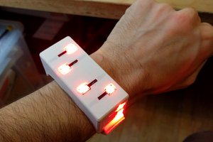
 Nicholas Stedman
Shoulda used a -- oh, wait...