 ABrugsch
When the original Pi Zero came out it wasn't offered with wireless at all (or a camera port even) but it didn't take long for third parties to create Wifi and bluetooth adapters and Redbear launched a kickstarter to create a the IoT HAT (which later had to be called pHAT because RPi foundation won't allow/extend the HAT name to Zero-sized boards.)

If I hadn't already soldered a non-w zero to my LCD board I would have just used a Pi Zero W (wireless) for this project, but I backed the IoT pHAT in kickstarter and had it unused ever since it arrived and it's been in my bits bag/box ever since (and I'm trying to actually use some of my purchases now, so this project seems a perfect fit.)
Being a HATpHAT means it has an eeprom containing the necesary overlay information to autoconfigure at boot time without all the nasty mucking about with hyperspace config.txt. So I just solder up the headers and away we go. Set up wpa_supplicant.conf and we're done KTHXBAI.
Ok next time on... wait. what? you don't believe me?
Yeah ths is a hackaday project. OF COURSE it didn't JUST WORK ;)
First the pHAT needed to be WIRED to the LCD board (not snapped on to the Pi as the available pins were broken out after the screen took the required SPI (sole use) and some additional control pins) and I'm sure there won't be any pin conflicts... (spoiler alert... There were conflicts!) So knowing that the Wireless chip wasn't going to need a full 40 pin connection, lets have a look at what pins need to be wired up.
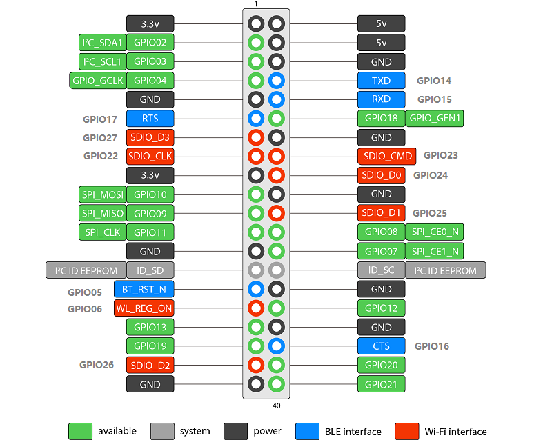
Anything in green is not needed, and as long as one Ground and one 5v (I already checked, the pHAT has it's own 3.3v regulator so doesn't need to tap 3.3v as well) all of the RED, GREY and BLUE pins need to connect. I know I want a few other interfaces made available (I2C, I2S etc) So let's see what the screen takes:
SPI: GPIO 7,8,9,10,11 also D/C on GPIO24 and RESET on GPIO25.
[looks at above pinout] all fine except 24 and 25... aww nuts. These are hardwired on the interface PCB. no problem, I'm had wiring the pHAT so I can just reassign SDIO to another alternative location with an overlay...
NOPE! SDIO only has one location on the main 40-pin header. There is an ALT on the full GPIO set on a Compute modue, but we're not using a compute module. Boo. I has a sad. which means..... BODGE WIRE TIME!
D/C and Reset are assignable to any free GPIO in the FPTFT driver, you simply set it as an option in commandline.txt so any of 12, 13, 19,20 and 21 are usable. So Lets go HACKING.

Just needed to cut 2 traces, solder some bodge wire from the pHAT to the DC/Reset Vias (blue wire) and direct solder to the DC/Reset points on the ribbon cable to their new GPIOS 20 and 21. then everything should JUST WORK (tm)...
But of course it's Hackaday, and no it didn't...
Discussions
Become a Hackaday.io Member
Create an account to leave a comment. Already have an account? Log In.