Close
0%
0%

Rotary phone musings

Yet another place where I store the data gathered while rediscovering a century-old technology.

Similar projects worth following
Playing with relays is not enough, old electromechanical phones embed pretty nice tricks that I'd like to understand and harness for future projects :-)
So this project is mostly a dump of the data I collect.

In 2014, Simon Winder made a fully electro-mechanical square root calculator :

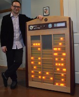
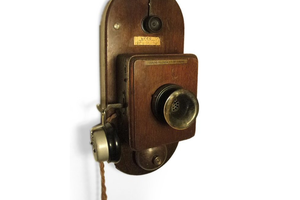
The number input uses a rotary phone dial. Then recently I found an oooold phone in the recycling zone :

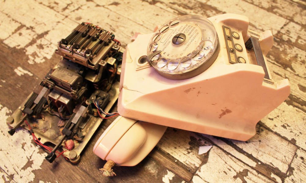
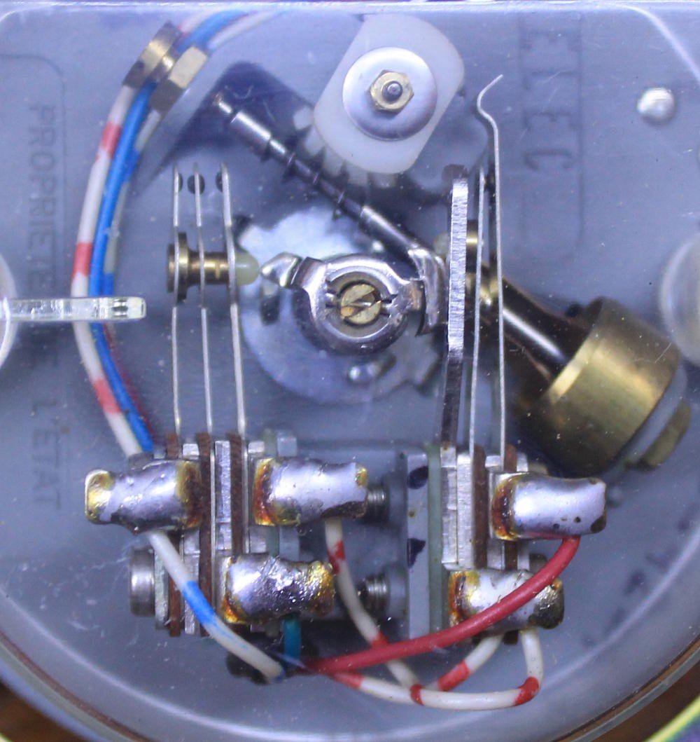
Unfortunately the poor puppy is FUBAR and the dial isn't reliable... So off to eBay and for 16€ I get a cheap Ericsson-made French model ("SOCOTEL n°24" ?) from about 1978 it seems. Here is how it looks under the hood:

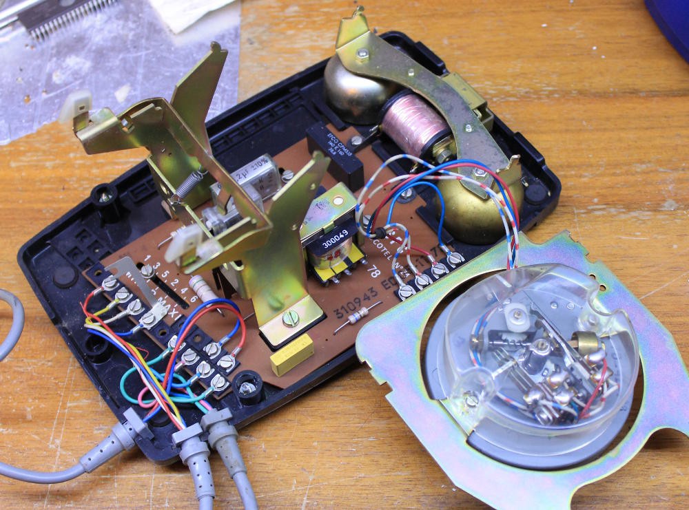
Apart from the cut cord, the whole thing looks well preserved, in working order, easily serviceable, and provides a powerful ring system in addition to the dial !


Today I want to use that type of interface for some of my projects :-) The principles are explained in a bunch of videos and pages, such as :

or Wikipedia :

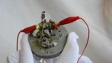
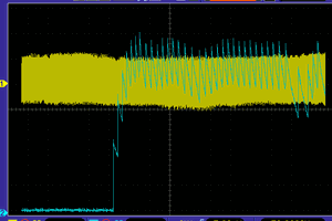
So the principle is very simple, with 2 contacts to manage :

  • The pulse contact that sends the "10PPS" signal : that's 10Hz, 100ms per period and about 50ms pulse length
  • The "active" contact that signals a number is being dialed.

Easy, right ?

But there are a few subtleties to get right before going further.

  • Make it ring !

    Yann Guidon / YGDES12/16/2020 at 15:46 0 comments

    Having the dial reverse-engineered is one half (of one half of ...) of the adventure. Detecting the "hook off" condition is pretty easy with the large switch, and the loudspeaker is easy to spot as well. "La pièce de résistance" is to make it ring...

    Wikipedia has some useful info about the external behaviour and protocol but nothing beats getting your hands (and tools) on the circuit itself. It must be noted that the ringing coil is in series with a 2.2µF high voltage cap and a resistor, because this branch gets a low frequency high-voltage sine kick in the face, to actuate the alternating hammer.

    The coil has about 1KΩ resistance so this must be taken into account in the t=RC equation that gives the max. rate of hammering.

    The coil seems to be polarised because it requires feeding 12V in one direction to hammer one bell, then in the other polarity to hammer the other bell. Apparently 12V is the lowest safe working voltage.

    ------

    From there, the path to ringing the bell seems to indicate something like a H bridge powered by a 12V PSU, but I'm not sold on the idea because I don't think I have a L293 in stock. I'm also very concerned by the inductive effects so I'm trying another approach.

    ------

    The coil requires about 24V of swing so let's give it : the first step is to build/devise a medium-impedance power supply, and a 9Vac wall wart does the trick. 2 diodes and 2 capacitors generate 31V from two opposite half-wave rectifiers. An additional filtering capacitor is added for good measure and voilà, you have a nice high-voltage supply. I don't know why I get >31V when I expected 25V, it might be due to extra harmonics on my mains line.

    From there we can drive the ringing coil, this time through a capacitor. 33uF seems to be fast enough though the telephone circuit itself has a 2.2µF capacitor that could be recovered. The capacitor blocks the DC current that would reach 30V/1KΩ=30mA otherwise. It also helps the coil get the pulse in both polarities.

    Driving the capacitor was the last challenge. I have burned half a dozen of transistors trying to make a "normal" push-pull circuit to work. I finally used a "dual emitter follower" circuit, which works well thanks to the very comfortable margin of the PSU (this type of circuit can't reach within Vbe of either rail).

    Then the driver is controlled by a simple push-down NPN transistor to the 0V rail, for ease of control with another circuit.

    I know it could be simpler, and D3 & D4 are not required because it's not an audio amplifier and it should "break before make", but it works well for me :-)

    Voilà !

  • Pulse dialing in practice

    Yann Guidon / YGDES10/09/2020 at 01:33 0 comments

    I found several videos that integrate the pulse dial system to input a code that triggers reactions. Mostly these are controlled by an Arduino board. One specific use if for escape games.

    .

    .

    .

    .

  • Detailed analysis of the SOCOTEL dial mechanism

    Yann Guidon / YGDES10/09/2020 at 00:12 0 comments

    The phone I use contains a dial with a series of contacts but only 4 wires.

    • Blue
    • Blue-white
    • Red
    • Red-white.

    The mechanical system is more complex however. Here is how it looks when at rest:
    There are two parts:
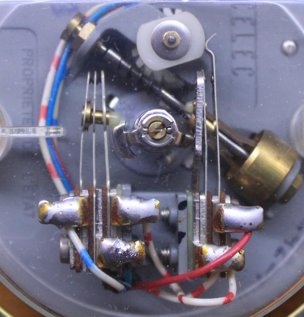
    • The left group detects when dialing occurs. It has 2 contacts that are normally open and connected to the blue wire.
    • The right group generates the pulses, with a normally closed switch, connected to the red switch. It is however forced "closed" at the end of the rotation.

    Here is how it looks during dial:

    The most interesting feature/trick is how the left group steers the signal for the right group, because the red-white wire is connected to both.

    The Blue wire is in the middle contact, blue-white on the left and red-white on the right. The spring mechanism ensures that the Blue/Blue-white (right) contact is closed before the Blue/Red-white contact when dial begins, and after when the rotation ends. So Blue is closed during operation.

    This is easily verified with a multimeter but a problem arises : the signal does not look clean. There is a high resistance when I can get it to work and a drop of at least 100mV so this contact needs cleaning. Which might explain why this device was discarded after more than 40 years of existence...

    Scratching the contacts restored the current. The system is stored in "open contact" position so it would oxidise with time. OTOH the Red/Red-white contact is normally closed and the contact is good (very low resistance) so the signal is quite clean.

    Through the Red-white link, both sides are connected and Blue-white can be substituted to Red-white in the tests (when the contacts are clean).

    • Blue-white is the common contact
    • Blue is the dial signal
    • Red is the pulse signal.

    Testing is believing !

    .

View all 3 project logs

Enjoy this project?

Share

Discussions

Dan Maloney wrote 10/09/2020 at 20:19 point

I used to love fooling around with old telephones. Those things were built like tanks! Glad you're keeping the flame alive, as it were.

  Are you sure? yes | no

Yann Guidon / YGDES wrote 10/09/2020 at 20:22 point

Legend claims I disassembled my first phone at age 5 or 6... I barely remember it though but it's not far from it :-)

And yes these were great machines ! They look so tame and simple to me, now.

  Are you sure? yes | no

Similar Projects

Does this project spark your interest?

Become a member to follow this project and never miss any updates