 Yann Guidon / YGDES
Having the dial reverse-engineered is one half (of one half of ...) of the adventure. Detecting the "hook off" condition is pretty easy with the large switch, and the loudspeaker is easy to spot as well. "La pièce de résistance" is to make it ring...
Wikipedia has some useful info about the external behaviour and protocol but nothing beats getting your hands (and tools) on the circuit itself. It must be noted that the ringing coil is in series with a 2.2µF high voltage cap and a resistor, because this branch gets a low frequency high-voltage sine kick in the face, to actuate the alternating hammer.
The coil has about 1KΩ resistance so this must be taken into account in the t=RC equation that gives the max. rate of hammering.
The coil seems to be polarised because it requires feeding 12V in one direction to hammer one bell, then in the other polarity to hammer the other bell. Apparently 12V is the lowest safe working voltage.
------
From there, the path to ringing the bell seems to indicate something like a H bridge powered by a 12V PSU, but I'm not sold on the idea because I don't think I have a L293 in stock. I'm also very concerned by the inductive effects so I'm trying another approach.
------
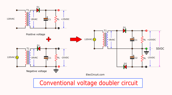
The coil requires about 24V of swing so let's give it : the first step is to build/devise a medium-impedance power supply, and a 9Vac wall wart does the trick. 2 diodes and 2 capacitors generate 31V from two opposite half-wave rectifiers. An additional filtering capacitor is added for good measure and voilà, you have a nice high-voltage supply. I don't know why I get >31V when I expected 25V, it might be due to extra harmonics on my mains line.
From there we can drive the ringing coil, this time through a capacitor. 33uF seems to be fast enough though the telephone circuit itself has a 2.2µF capacitor that could be recovered. The capacitor blocks the DC current that would reach 30V/1KΩ=30mA otherwise. It also helps the coil get the pulse in both polarities.
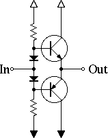
Driving the capacitor was the last challenge. I have burned half a dozen of transistors trying to make a "normal" push-pull circuit to work. I finally used a "dual emitter follower" circuit, which works well thanks to the very comfortable margin of the PSU (this type of circuit can't reach within Vbe of either rail).
Then the driver is controlled by a simple push-down NPN transistor to the 0V rail, for ease of control with another circuit.
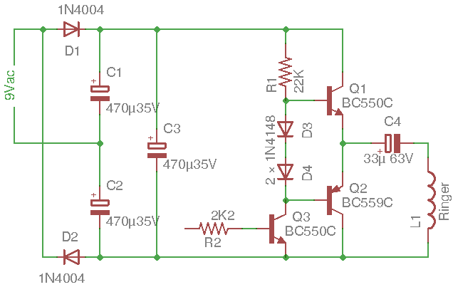
I know it could be simpler, and D3 & D4 are not required because it's not an audio amplifier and it should "break before make", but it works well for me :-)
Voilà !
Discussions
Become a Hackaday.io Member
Create an account to leave a comment. Already have an account? Log In.