 Mr.Else
This post is dedicated to the first prototype, which I used reliably for about 1 year. In this version of the garage there was no connection to home assistant or the local network. An advantage of this version is that it works independent from network failures etc. On the other hand in this version the flap remains open as long as the vacuum cleaner robot is on the road.
Electronics:
The general setup is quite simple. A LDR is used to access the status LED of the docking station from the vacuum cleaner robot (see previous Log). As soon as the LED is ON a NoedMCU registers the change of the LDR signal and gives the servos the instruction to open the flap. I also added a switch for opening the flap, a switch for closing the flap and a LED that lights up when the flap is open.
The setup is shown in the picture below (Note that the switch and the LED is not attached in the picture below):
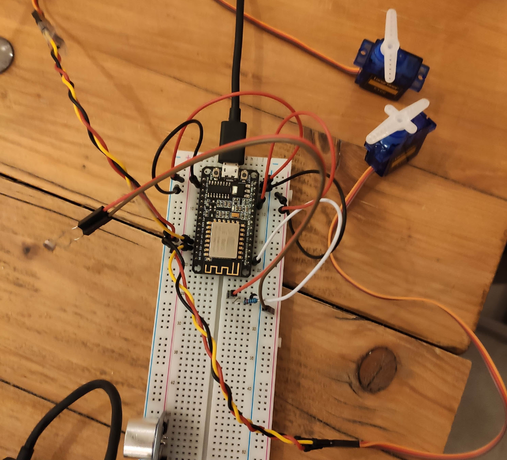
The according code is printed below. There is a lot room for improvement (e.g. instead of letting the garage door bump down like a stone let it go down smooth) but it works. The appropriate NodeMCU pins can be found as comments in the code.
#include <Servo.h>

Servo servo1;
Servo servo2;

const int ldrPin = A0;
int ledPin = 2;  //Set pin for LED Light ESP D4

int switchOpen = 14;  //D5
int switchClosed = 12;  //D6

void setup() {

  Serial.begin(115200);

  pinMode(ldrPin, INPUT);
  pinMode(LED_BUILTIN, OUTPUT); // set the digital pin as output.
  pinMode(ledPin, OUTPUT); // set output for LED

  pinMode(switchOpen, INPUT_PULLUP);
  digitalRead(switchOpen);
  pinMode(switchClosed, INPUT_PULLUP);
  digitalRead(switchClosed);

  servo1.attach(4); //D2
  servo2.attach(0); //D3

  //servo1.write(10);
  //servo2.write(10);
  delay(2000);

}


void loop() {


  int ldrStatus = analogRead(ldrPin);   // read the input on analog pin A0
  Serial.println(ldrStatus);   // print out the LDR value


  if (digitalRead(switchOpen) == LOW) {
    ServoOpen();
    Serial.println("Servo Open via Switch");
  }

  else if (digitalRead(switchClosed) == LOW) {
    ServoClosed();
    Serial.println("Servo Closed via Switch");
  }

  else if (ldrStatus <= 100) {
    ServoClosed();
    Serial.println("Servo Closed via Sensor");
  }

  else {
    ServoOpen();
    Serial.println("Servo Open via Sensor");
  }
}


void ServoOpen() {
  servo1.attach(4); //D2
  servo2.attach(0); //D3
  servo1.write(5);
  servo2.write(120);
  digitalWrite(LED_BUILTIN, LOW);
  digitalWrite(ledPin, HIGH);
  delay(250);
  servo1.detach();
  servo2.detach();
}


void ServoClosed() {
  servo1.attach(4); //D2
  servo2.attach(0); //D3
  servo1.write(120);
  servo2.write(5);
  digitalWrite(LED_BUILTIN, HIGH);
  digitalWrite(ledPin, LOW);
  delay(250);
  servo1.detach();
}
Hardware:
For the frame I made a simple gate out of wood. The electronics were attached to it.
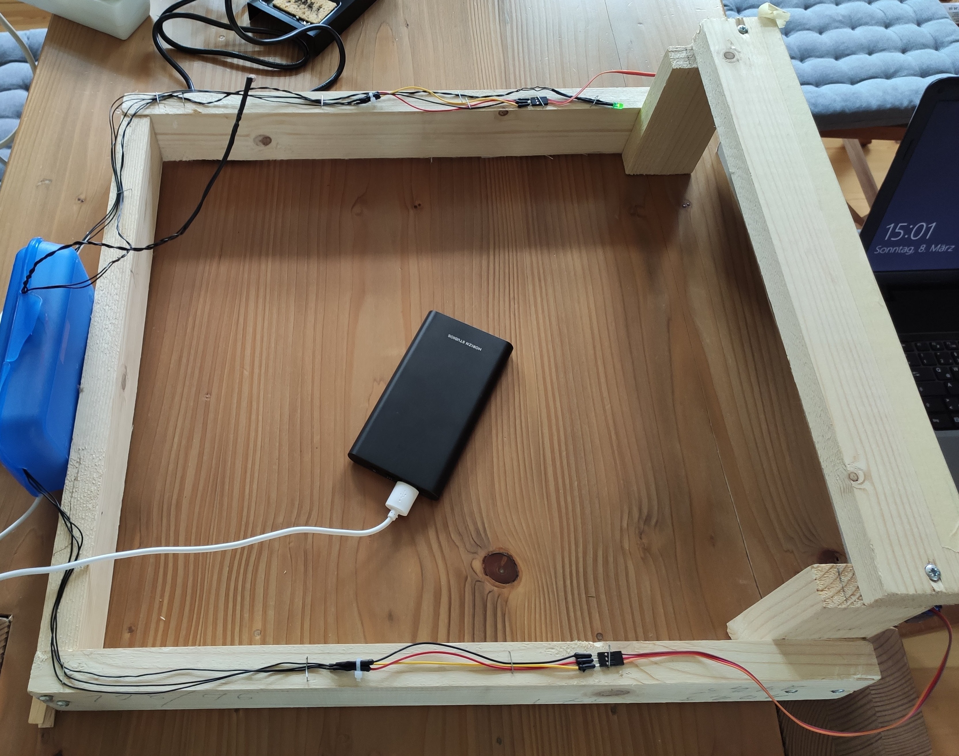
The servos are held in position by simple screws. Not really pretty but functional. I also painted the frame black. As servo arm I used a threaded rod and cable ties. Unfortunately I had nothing better at hand. It's really time for a 3D printer!
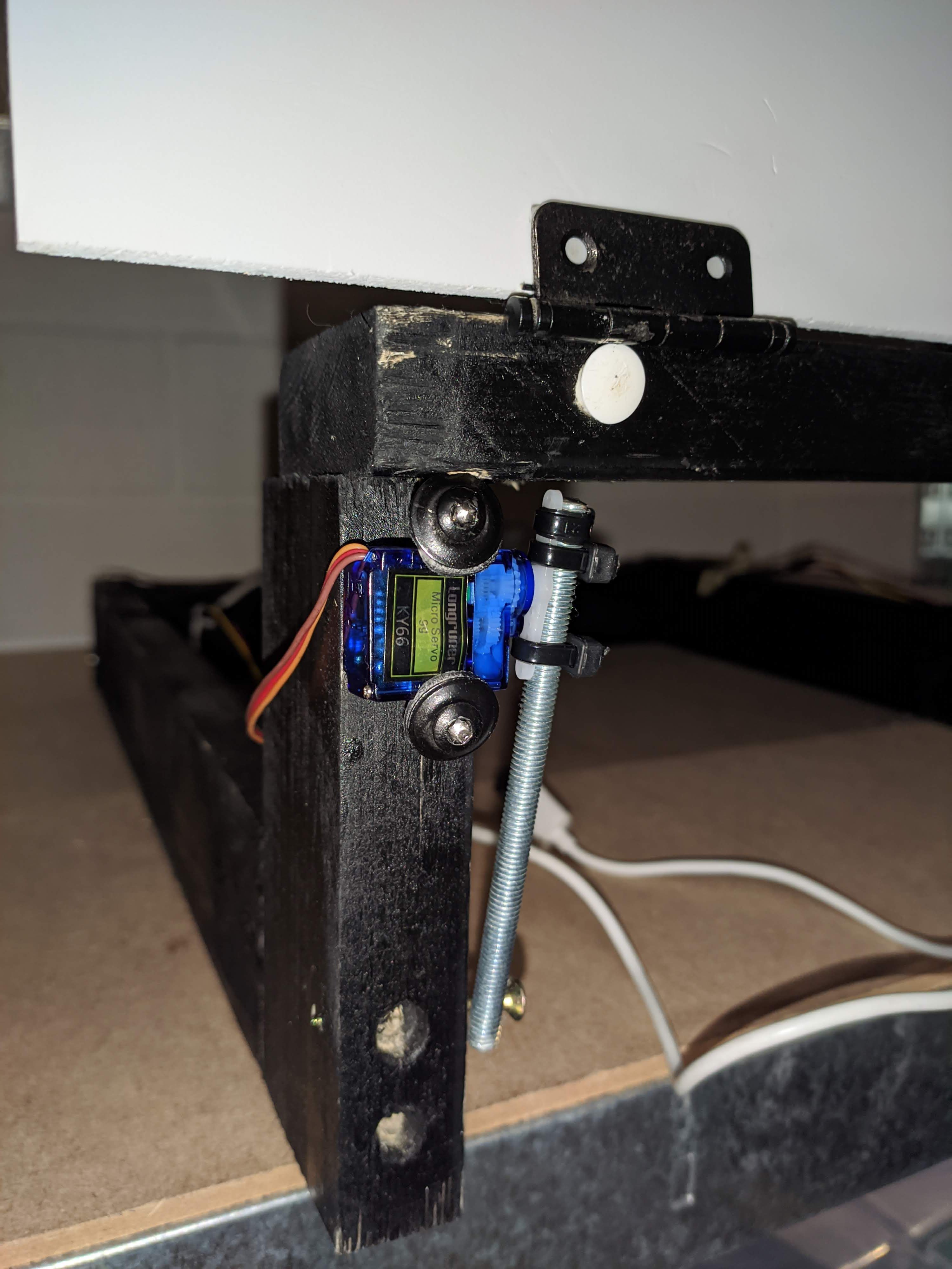

The door was made out of 3 mm rigid foam board. This material was light enough to be lifted by the SG90 micro servos.
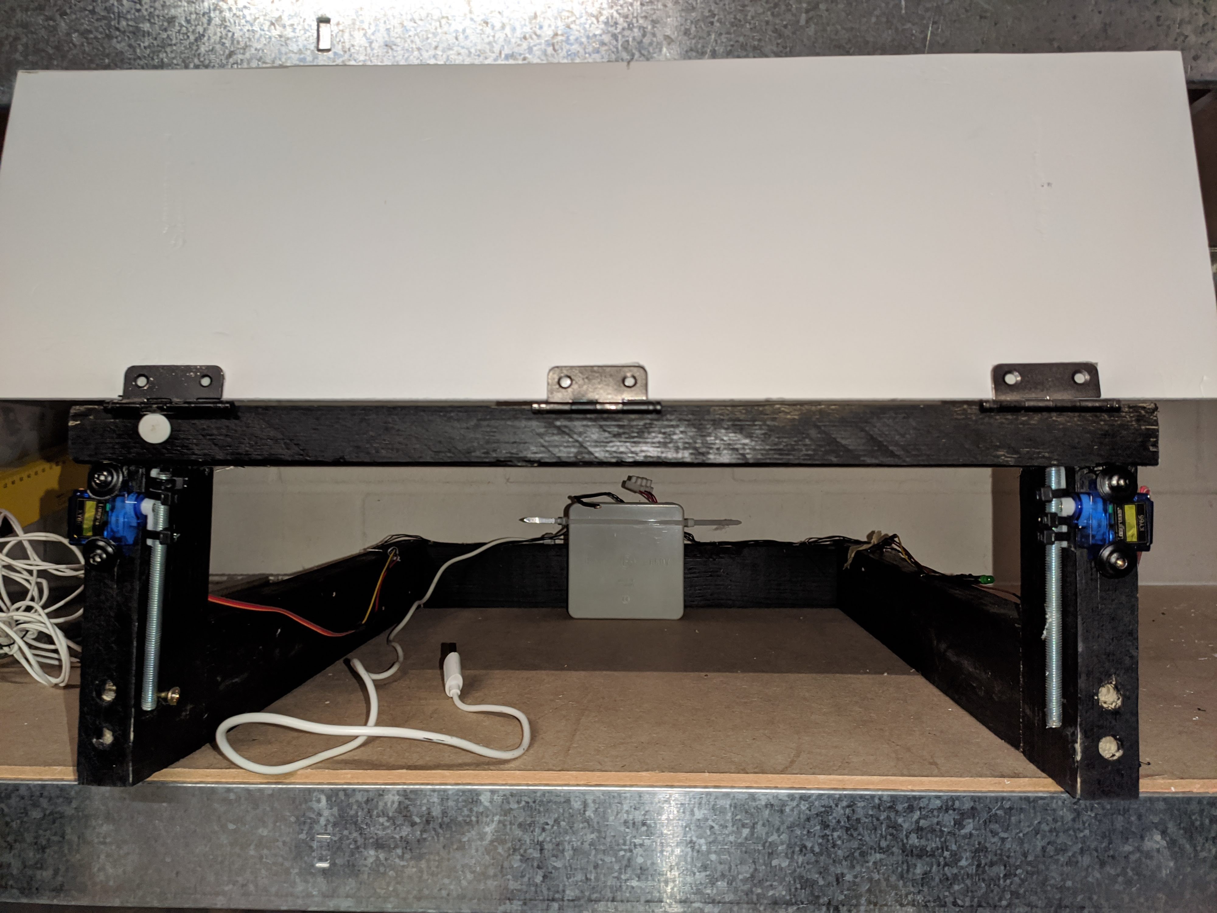
The whole setup was then installed under the kitchen cabinet.
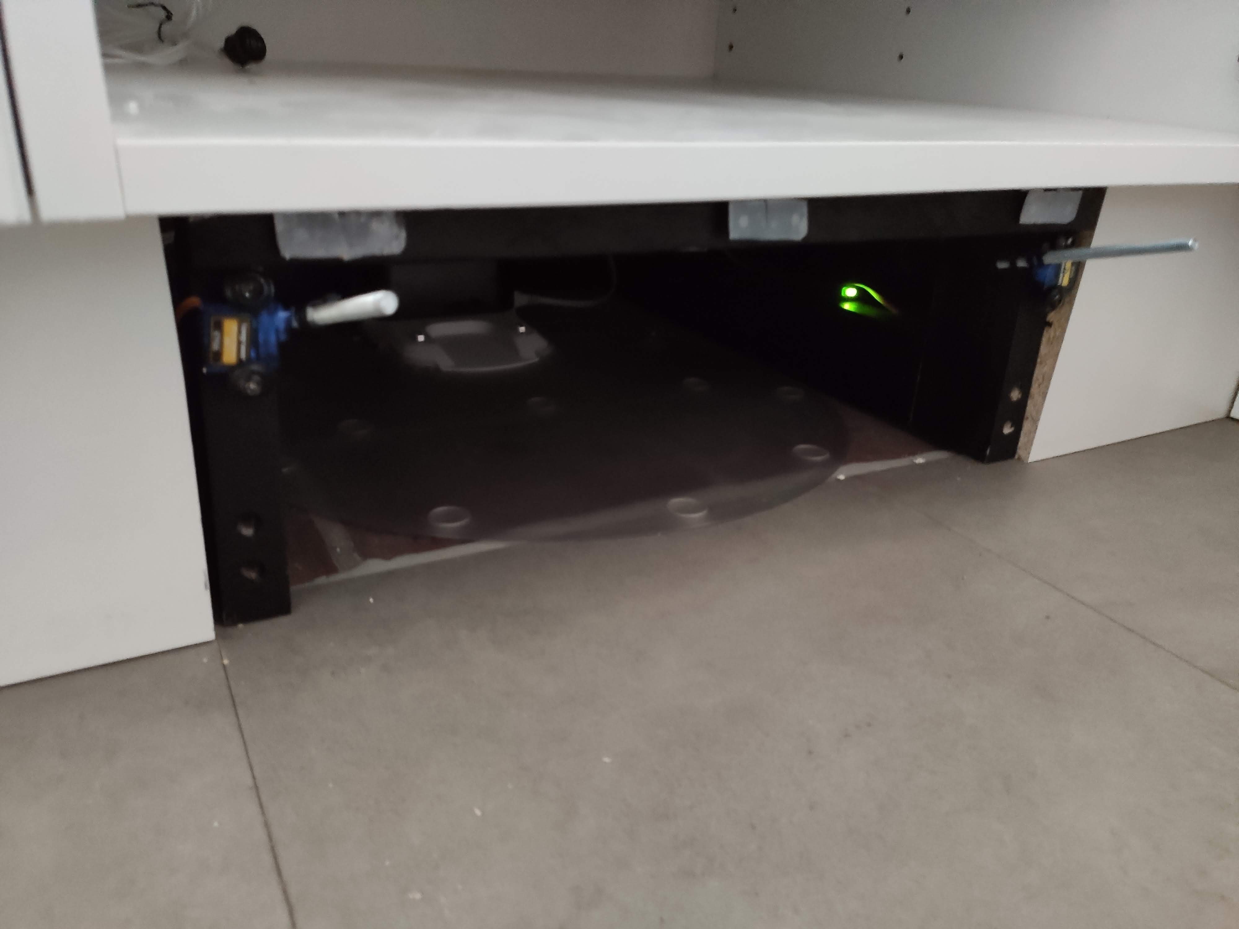

See the video below for the complete setup in action. Note that the door stays open while the vacuum robot does its job.
Discussions
Become a Hackaday.io Member
Create an account to leave a comment. Already have an account? Log In.