This is an attempt to dissect and to understand how these little handheld NOAC (Nintendo-on-chip) consoles that are being sold for around $5 in the market.
You can read more about the NOAC on the Wikipedia page: https://en.wikipedia.org/wiki/Nintendo_Entertainment_System_hardware_clone
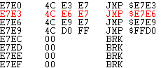
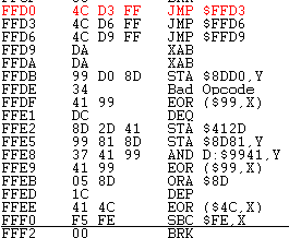
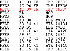
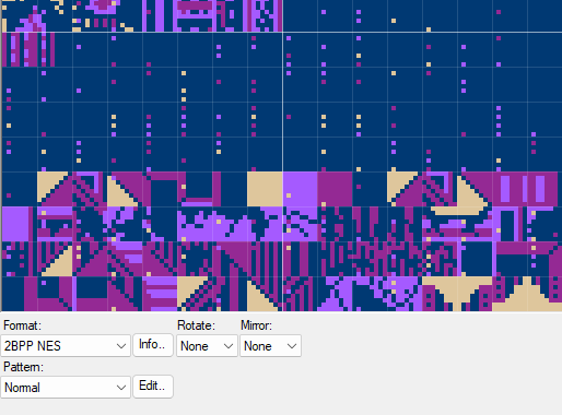
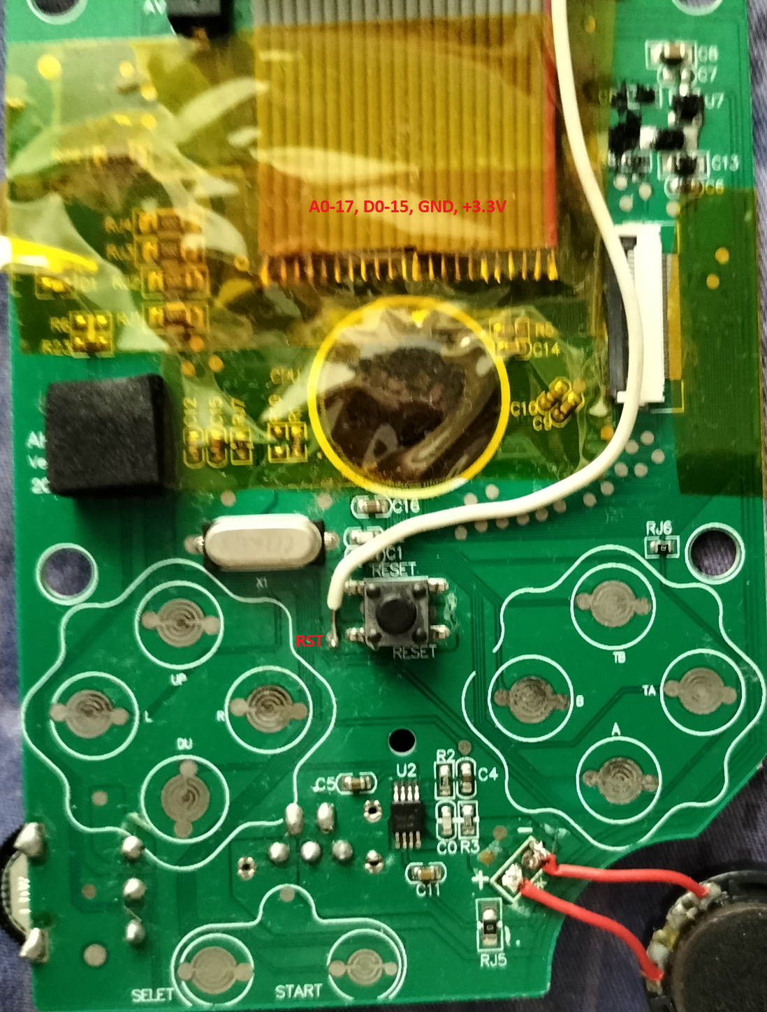
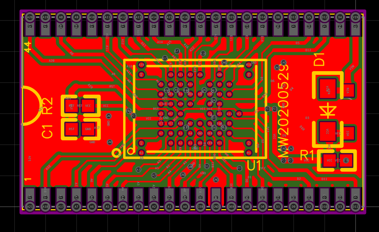
We know that this thing in the black epoxy has the clone of the Nintendo Entertainment System. Upon further reading, there's more to being the clone too - possibly an enhanced version like the VT-series (http://www.vrt.com.tw/datasheet.htm).
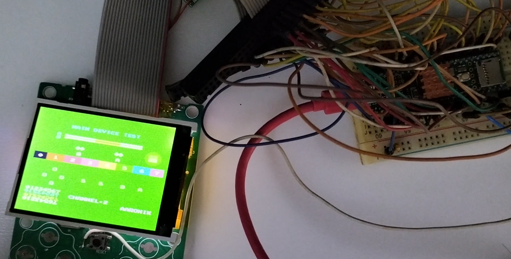
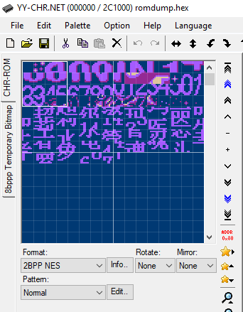
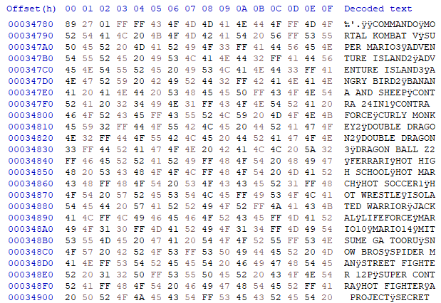
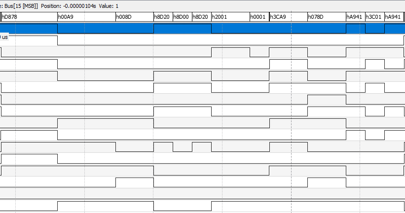
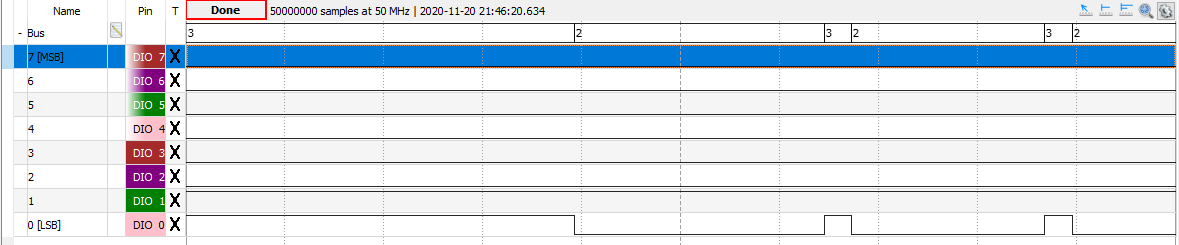
What's inside it? How does it work? Could I load its ROM another new code? That's the question!
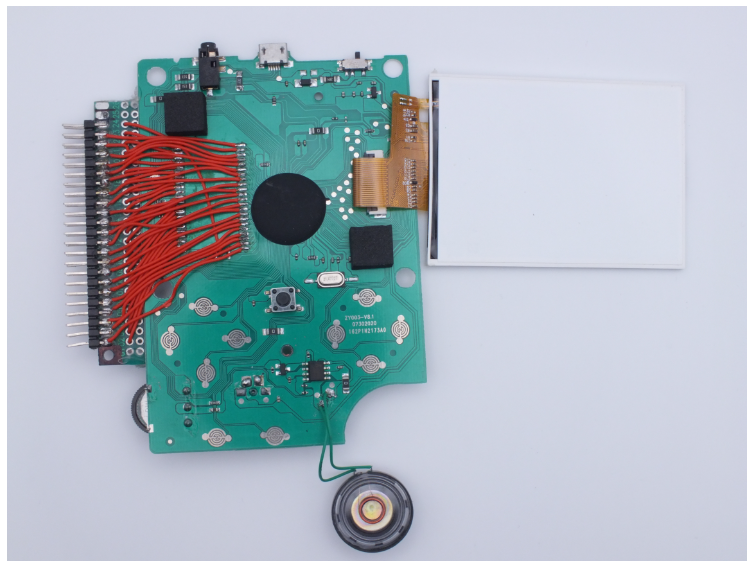
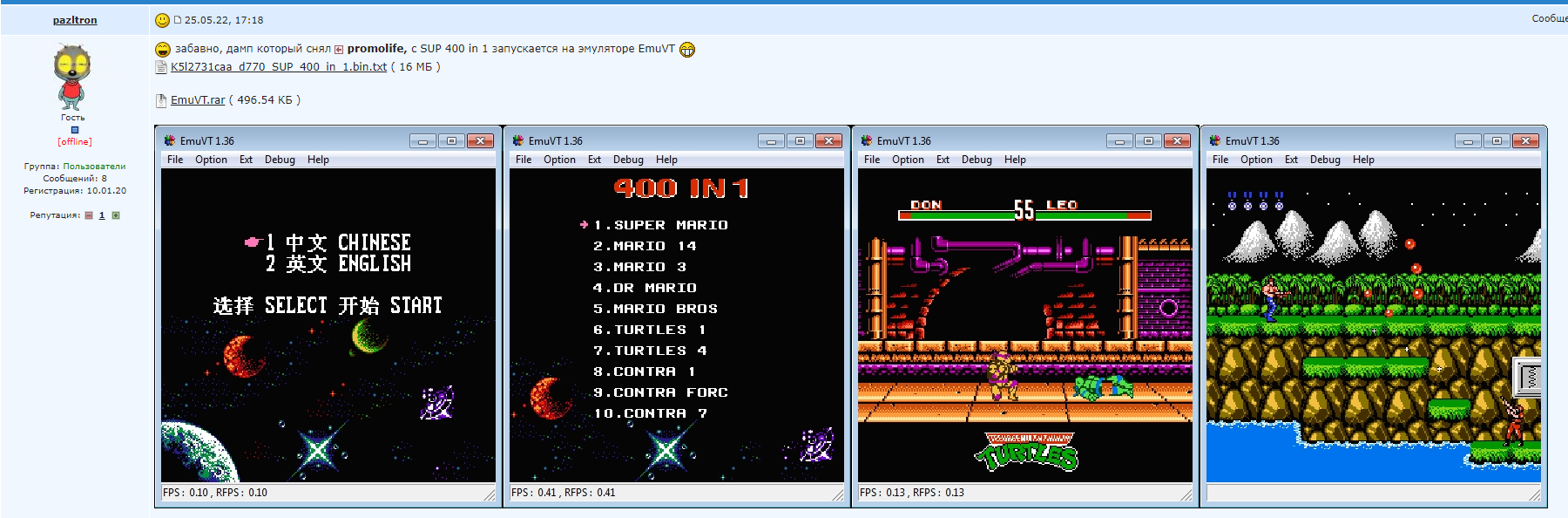
 (Source: Thanks to Aleksandr Serdyukov -
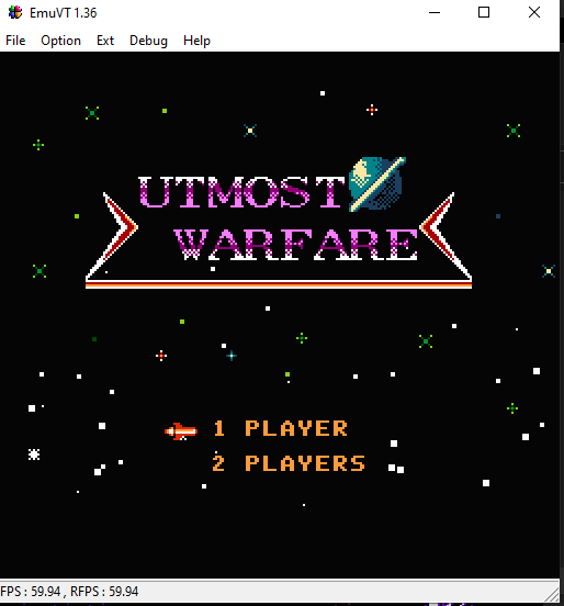

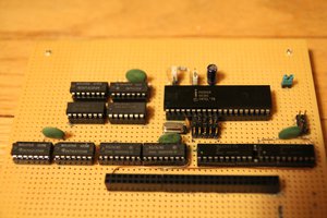
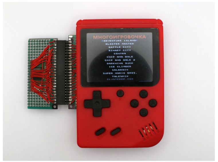
 Bentendo64
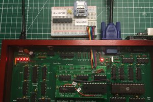
 Marcel van Kervinck
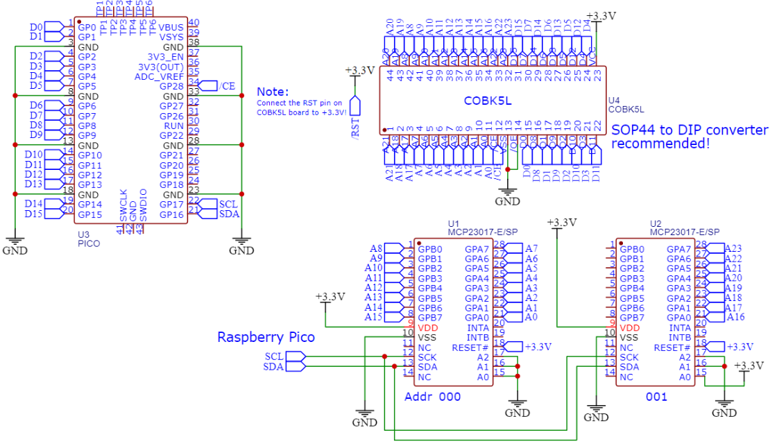
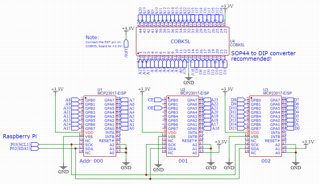
one small questions. Is possible replace cpu to arm cortex-m or raspberry pi pico