Background:
When hackaday announced the circuit sculpture challenge in august I was very excited. I was already impressed by Mohit Bhoite's sculptures on hackaday and his interview on embedded.fm (ep 314) really encouraged me to give it a try. So what better excuses than a hackaday contest.
Never having made a sculpture before I thought it be wise to do a basic tutorial for one first (the link in the embedded.fm shownotes was very helpful). Trying things for the first time not being challenging enough I thought it would be fun to try this as a date.
On this date we learned the following:
- Cutting mats are not heat resistant
- You will need up to 4 hands to complete some connections
- Double sided tape is not ideal.
- SMD LEDs like to stick to soldering iron tips
- Soldering is a fun date activity
Most circuit sculpture tutorials recommend holding parts in place with double sided tape. However the heat of the soldering iron will reduce the stickiness of the tape (to not sticky at all anymore). So the need for a solder-able hold in place method was born.
I like to hobby a lot with soft robotics projects which (for me) are made of silicone. Because silicone is quite heat resistant the idea of using as a jig cam e to mind. When pouring silicone you will almost always have a little left over which pools at the bottom of your mixing cup. When this eventually sets it forms a nice round complementary soldering pad. Trying to make another one of Jiří Praus' LED jewelries, but this time on my own, worked quite well even with just a flat silicone pad.
Since its possible to shape silicone in many ways when you actually pour it into a mold (instead of leaving it in the cup); the idea of making a pattern to hold the brass rods in place started to form. Later the realization came that the air pumps I was using for my soft robotics project could be used to create suction to keep SMD components in place.
Leading to the project page we are on now. I had a complicated idea for a circuit sculpture in mind for the contest, however working on the jig itself became quite interesting and challenging. I also hope that by making this project page I can receive some input from other circuit sculpture builders. Mainly about what parts are often used and difficult to work with without a jig, also for which orientations solder support is appreciated. Plus feedback on the OpenSCAD is also appreciated. I am really curious what people think about the variable naming scheme, since I'm personally really fond of it.
OpenSCAD file
Naming scheme for variables is based on parts of a city. Code is now on Github, though it still needs development in order to produce a useful jig.
| Variable names above ground | Variable names underground |
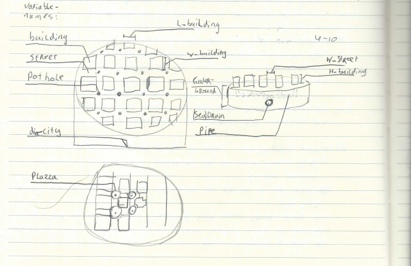 | 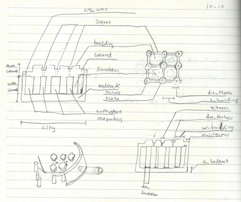 |
Keep in mind that the current physical build is far from perfect. The 3D model code is also quite inefficient since it takes both a long time to render as well as to preview. The concept of this jig is great, however there is a lot to improve before it's ready help anyone. But I believe the soft soldering jig can help with circuit sculptures.
Model versions
V0
This was the prototype version, to see if the concept even works. Area is deliberately very small for rapid printing and less silicone use. The airflow works and keeps 1206 LEDs in place. This jigs is surprisingly useful already. Even for non circuit sculpture stuff like soldering wires to each other.
Mold consist of 2 parts. The cylinder containing the city topology and a plug to be inserted to claim the space later occupied by the air tube. Plug can be held in place by elastic band.
| V0 jig model | V0 mold and result. |
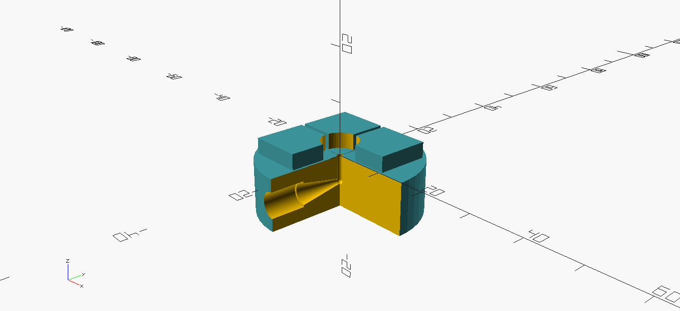 | 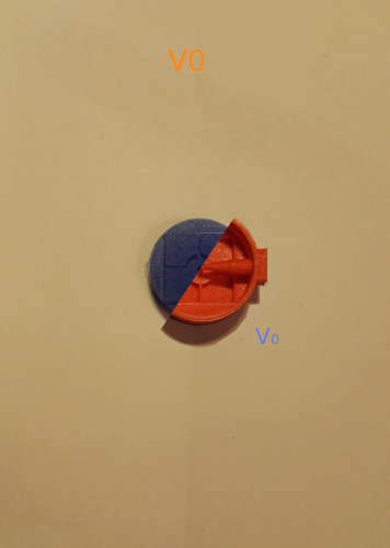 |
V1
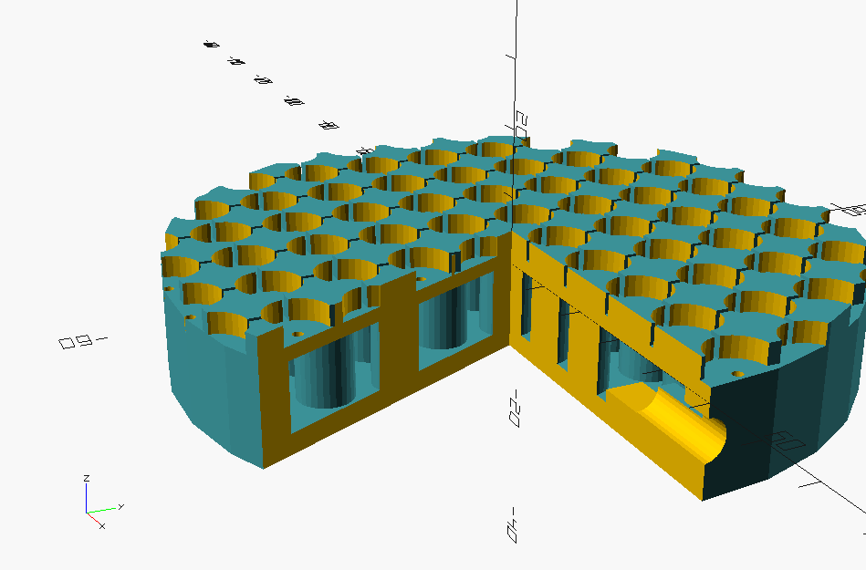
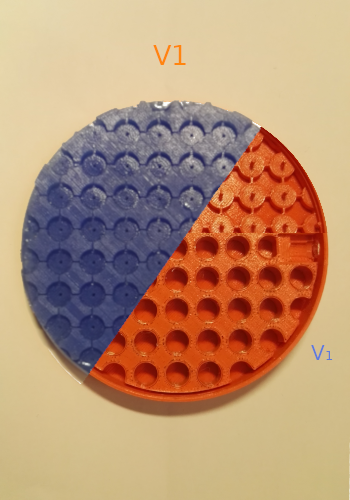
First full scale design. with lots of manholes for air intake. Unfortunately it could not create any suction since there where to many manholes. The bigger surface is great to keep longer rods in place.
Made with both shore 8 and shore 15 silicone. Both having a nice firmness. Though people seem to prefer the shore 15 (firmer one). I personally find I little bit to stiff, therefore next version I will try adding some silicone oil to make it a bit more flexible (between 8 and 15).
| V1 jig model | V1 mold and result. |
 |  |
V2
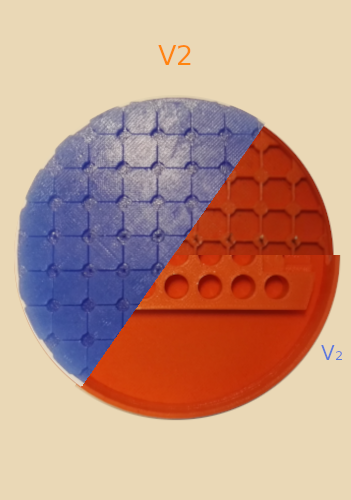
Trying to improve suction the number of manholes is reduced. Also reduced diameter of manholes by interesting brass rod pieces instead of printing them (which was at printer resolution limit anyway). Suction still doesn't work when using as is, however does work when plugging unused holes with brass rod.
Extreme warping of the surface is observable probably because the foundation is not firm enough to withstand it. Might need to use higher shore for bottom and top.
Jig v2 was made with shore 15 silicone plus 10% silicone oil (weight based). This strikes a good balance bot mold is also significantly easy to remove. As said above bottom foundation is not sturdy enough though, so might need higher shore anyway. Having to fill area without manholes greatly reduces silicone use.
| V2 jig model | V2 mold and result. |
 |  |
Foot pedal
There is a need to switch the air pump on and off for several reasons. When done soldering you want to pick up part without putting stress on SMD part for instance. Also while not being unbearable loud the sound the pump makes will get on your nerve after some time. Because we are already trying to take away responsibility for the hands a foot pedal seems to be a good match.
Actually a switch
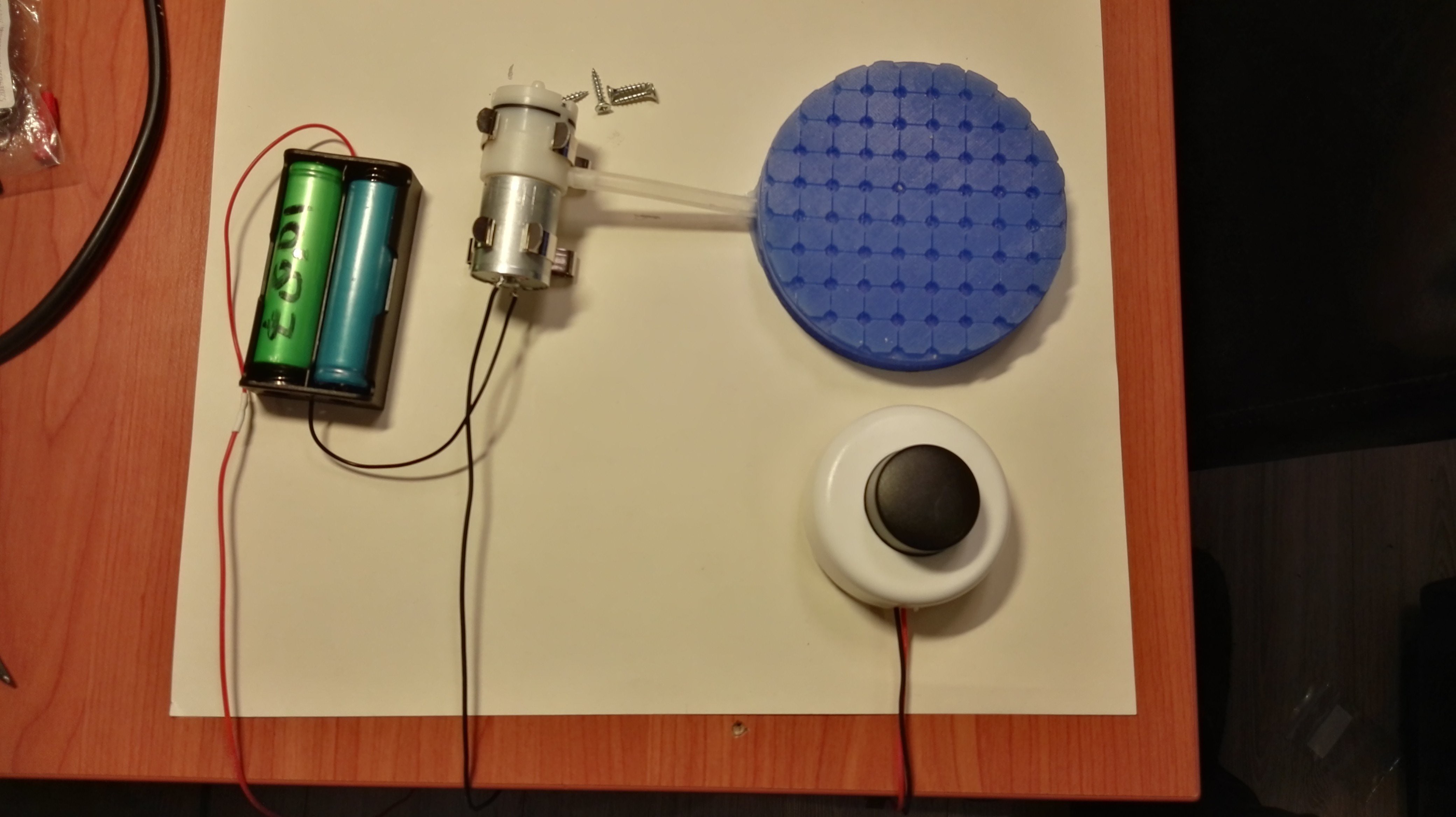
Because we just need to switch the pumps on or off and timing isn't super critical we can use a switch. One of those foot switches for lamps that available at the common hardware store seems a good fit, since its cheap robust and does the job. Its easy to wire up, just interrupt (with switch) the wire from either the positive or negative lead between battery and air pump.
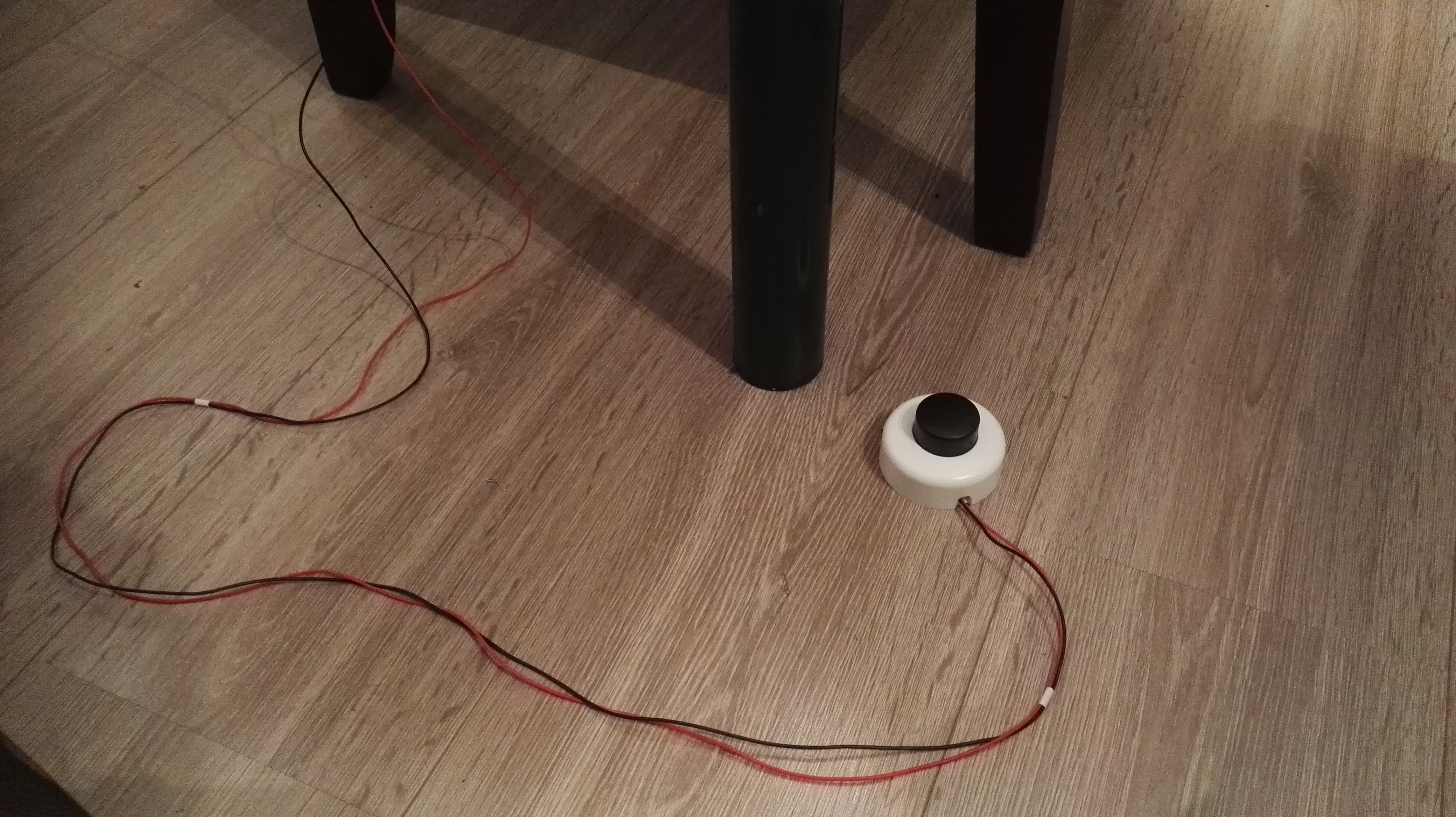 |  |
to do
- Make list of components to support
-
Vacuum pump control by foot pedal - design multi angle layout
- figure out how to support parts in Z plane
optimize OpenSCAD code- Maybe design some manhole covers (plugs to block airflow)
challenges to keep in mind
- Monitor how silicone reacts to the heat of repeated soldering
- Calculate airflow requirements
- OpenSCAD render times are getting too long
- Keep in mind what you actually want to do with this project page.
- Keep it somewhat concise.
Silicone used and heat resistance rating:
The silicone used is of shore A15 which is permanently heat resistant to 200C and short term heat resistant to 300C. While these is "high" temperatures soldering is usually done at 350-400C so our application is outside of the specs of the silicone used. There are types of silicone which are more heat resistant they are also higher shore rating (A45 -A60) which makes them unusable. Fortunately silicone does not meld or evaporate when its overheated, it mainly dries out and becomes more brittle. The way one usually solders also leads to relatively short exposure time to heat.
So the fact that the silicone was rated for quite "high" temperature and does not fail catastrophically (coupled with the fact that this was the silicone I already had on hand); let me to just try this silicone to see if it would work. Practice has to show in what way heat from soldering will pose a problem for this jig.
 Inne
Inne