Ken Yap
This is the board used to demonstrate the 6-segment font in 6 segments suffice. In the links section you will find a link to the Github repository containing the design files.
I have situated 2 digits per board. The board is cascadable to 6 digits with connectors. Only 6 segment drive lines and 6 digit drive lines are needed as the digits are multiplexed. In the top centre of this close up of the back you see how the digit selects work by routing the resistor lead into the appropriate through hole. You also see the cascade connectors on the left.
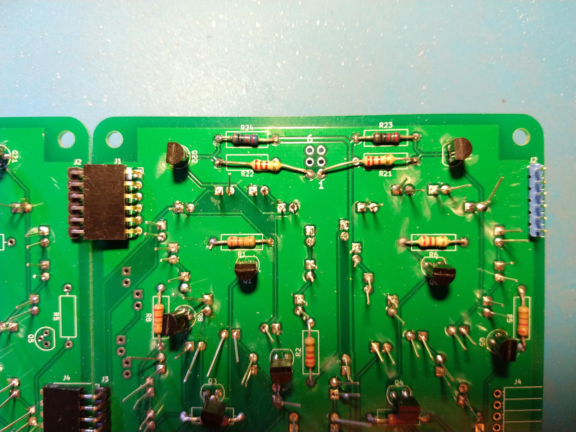
All the components are through hole with the exception of the optional constant current ICs which I didn't use in the end. Transistors are jelly bean TO-92 BJTs. LEDs are 3mm diameter. Note that the anode voltage has to be high enough to drive 4 LEDs in series, so 5V will not be enough.
I made a couple of small mistakes. The first was not taking into account the height of the power supply decoupling capacitor, as an MCU board is meant to piggy back onto the first two digits for a clock. I ended up laying the capacitor on its side. The second was the female connectors have the holes 2.54 mm above the board, but the corresponding male connectors have pins 5.08 mm above the board. I ended up soldering the female connectors slightly above the board. The lesson is I have to start paying attention to the Z axis in PCB design; hitherto I only worried about footprints.
If I were to do a revision (big maybe), I would make these changes to the font.
- Separate the digits a bit more.
- Make the diagonal a straight line. I curved it a bit to accommodate the curved digits but that ends up visually annoying.
- Squash the digits a little horizontally which allows for more interdigit space and also the diagonal will become steeper.
- Reduce the gap between the c and f segments, which shows up on the 5.

 drewrisinger