 Lance
LanceBackground
Historically, home electronics projects were done on prototyping breadboards and then hand soldered together for a permanent solution. In the last few years, events coalesced to allow makers to enter a domain of surface mount technology. Free or affordable design software like KiCad or Eagle lets anyone design PCBs using a home computer. Low-cost PCB manufacturers like JLCPCB, PCBWay, and Oshpark have made it possible for hobbyists to order small quantities of PCBs extremely cheaply. Assembling anything more than a board or two is still a hurdle, however. Doing it by hand is extremely time consuming and sending them to a manufacturer is very expensive.
A few manufacturers create small, pick-and-place desktop machines. However, these manufacturers also manufacturer commercial-grade machines that generate much higher profits. It's not hard to imagine that the low-end machines do not receive the attention needed to make them consumer-friendly. As a result, these machines are almost universally loathed by the community. The mechanical body (frame, rails, et cetera) of these machines is usually sufficient or even excellent, but the controllers and software tend to be terrible.
Fortunately for the community, open-source projects have stepped in to fill the void. Projects like Smoothieboard/Smoothieware provide the controllers and the OpenPnP project handles the software side. OpenPnP has grown into the unrivaled maker's choice of pick-and-place software.
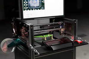
The maker community is now retrofitting existing hardware with open-source controllers and software as well as building custom machines from the ground up.
Objective
This project wouldn't have been possible without all of the fantastic work of the open-source community. I'm documenting what I've learned in order to contribute to the community. I'm hoping that something here will save the next person some time and frustration in dealing with the issues I've discovered along the way.


 Mika Heikkinen
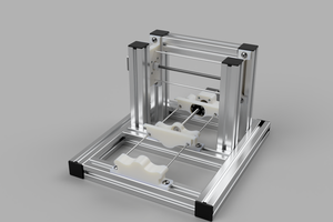
 Myles Eftos
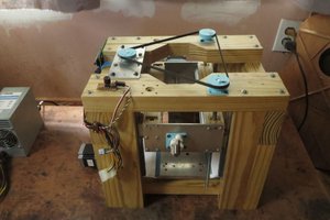
 dekutree64
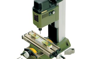
 Greg Duckworth