 Brainy.Baboon
I used to think choosing an op-amp was an easy thing to do. There are so many options. Surely there would be many that would fit my needs. I couldn't have been more naive.
Choosing a right op-amp, when you have little previous experience working with them, can be the most frustrating thing to do, especially when you are stuck at home and a global pandemic is raging.
I learnt that for portable systems the best approach was to use a single supply op amp because you can just connect the -V pin to ground and that really saves you a lot of trouble. If I had to use a dual supply op amp circuit then I would also have had to provide a regulated negative supply voltage. That meant adding two more voltage regulators and a lot of design complexity.
Many op amps can be used in both single and dual supply operations but most will not swing the output voltage very close to the supply. For example using the famous LM 741 in 5V single supply you will get a max output of 4.3 V and the lowest value the output will take is around 0.7 V. So you will lose out on a substantial part of the Arduino's dynamic range.
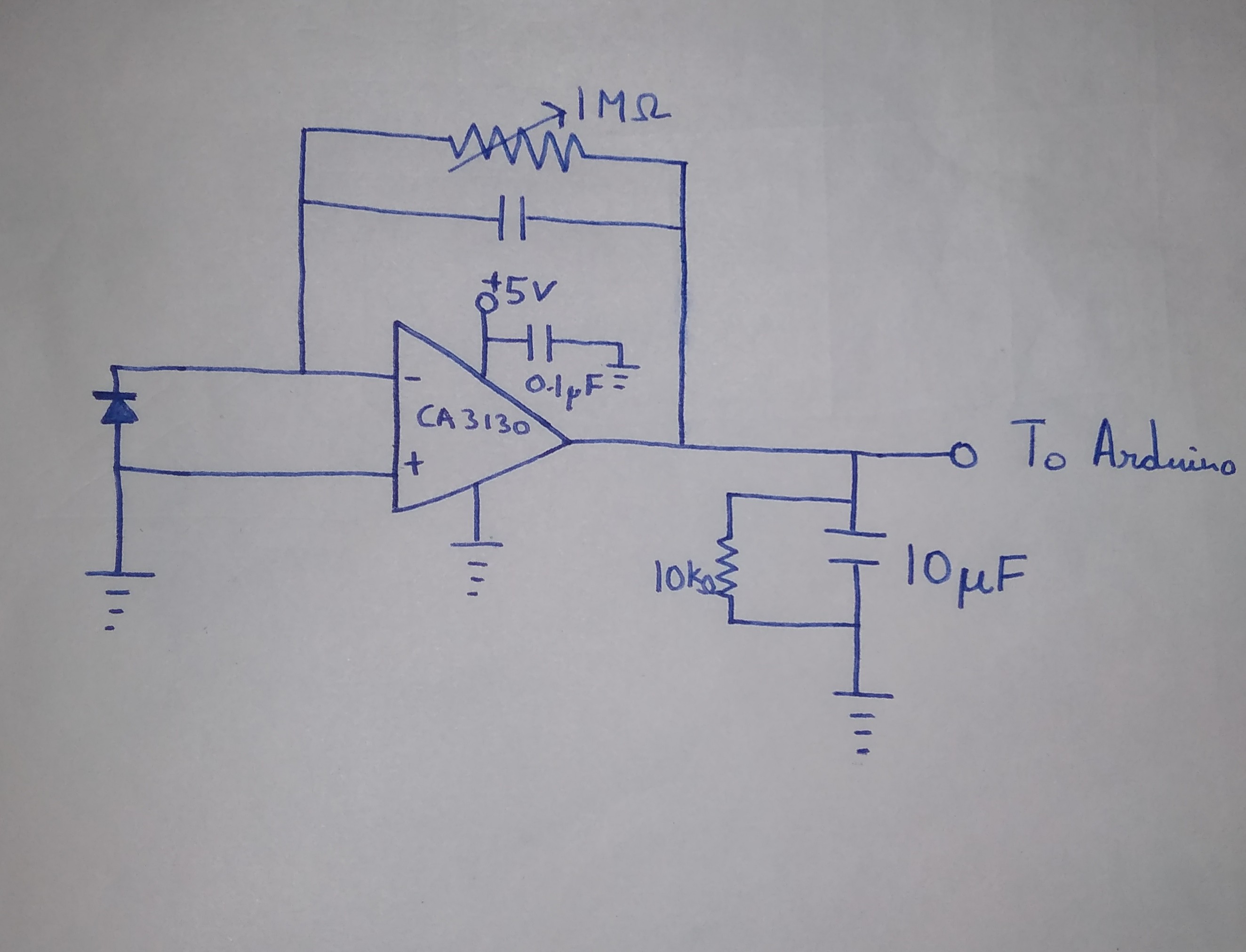
This is where CMOS op amps come in. They can swing their output voltages very close to their supply and ground so we can maximize the use of our Arduino's analog measuring range which is from 0 to 5 V(if you are using AVcc as analog reference). Microchip's application note on Using Single Supply Operational Amplifiers in Embedded Systems proved really helpful. Microchip also makes the MCP601/MCP602 op amps that are designed for use with the ATmega series of microcontrollers. I couldn't find a seller in my country and the cost of buying it from a foreign outlet was outrageous. I used the CA3130 op amp which is a lot cheaper and has similar characteristics. That being said I would recommend the MCP601 over the CA3130.
Most photodiode circuit guides would recommend using a very precise instrumentation amplifier such as the LTC 1050 but that raises the cost by a lot. Good in amps cost more than the AVR itself.
The other argument for not using it would be that it is redundant. The weakest link in the design when it comes to precision would be the photodiode itself. Using a better photodiode, like one from Hamatsu would justify the use of an expensive in amp but that is not what we are doing here.
The output drives a capacitative load of 10 microfarads.
Here is what the circuit looks like.
Discussions
Become a Hackaday.io Member
Create an account to leave a comment. Already have an account? Log In.