Brainy.Baboon
-
Yikes...... voltage spikes!
11/20/2020 at 21:29 • 0 comments![]()
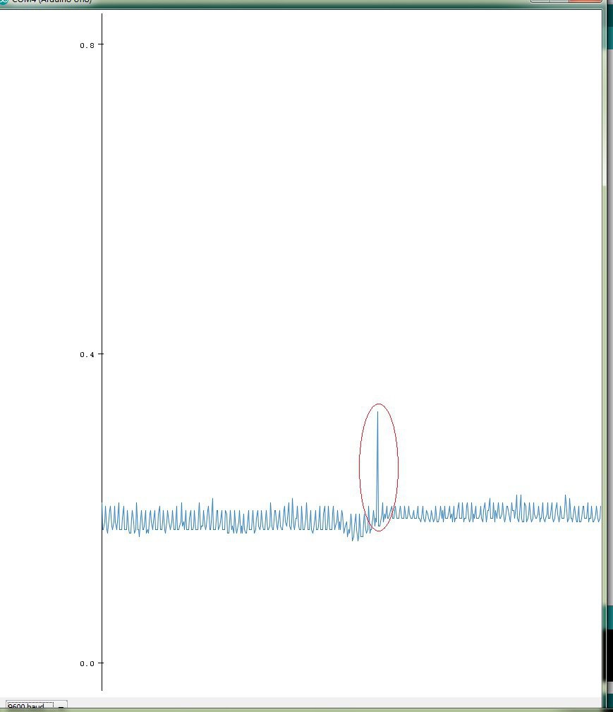
I was getting these huge output voltage spikes in the op amp output. I tried using different values for the decoupling capacitors but that didn't help. It turned out to be a dodgy connection on my breadboard which I had used to connect my 1000 micro-farad decoupling capacitor. I used another socket and the problem was gone.
While I was considering so methods to compensate for the spikes in software(because I was literally at my wits end and couldn't trace the problem) I came up with the idea of using exponential smoothing on the final signal. This would reduce the noise that we are left with after the oversampling and decimation. This technique would reduce response time but that is not a concern for us in our application.
-
Noise Reduction, Oversampling and Decimation
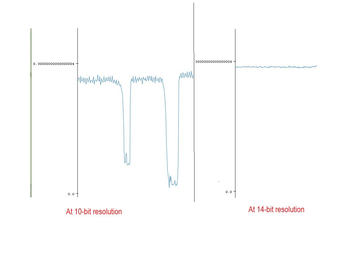
11/17/2020 at 19:31 • 0 commentsThe standard analogRead() function returns a 10-bit value which can range from 0 to 2^10(=1024). This is because the ATmega 328 has a 10-bit ADC. This means that the smallest value we can resolve if our range is 0-5V is 5/1024 or approx 0.005V. This may look like a good resolution but the datasheet mentions that the last two bits of that 10-bit isn't really reliable so we can probably be accurate up to 5/256 = 0.01V (provided we have compensated for all other sources of error). Now I don't like that. Thankfully there is a technique called oversampling which is really easy to use but gets neglected very often. The AVR application note 121 is really a better explanation of the concept than the Wikipedia article.
I used oversampling to get a 14-bits of resolution so I add up 4^n samples where n is the additional number of bits (which in this case is 4 so 4^4 is 256) and the bit shift the result to the right by n.
So the code looks something like this:unsigned long accumulatedReading =0; for(int i=0;i<256;i++) { accumulatedReading += LowNoiseRead(); // adding 256 readings delay(1); } return (accumulatedReading >> 4); // bit shifting to the right by 4Another important thing to remember is now that we a are getting a 14-bit value we need to make some changes to the way we interpret the results i.e. convert the reading into volts. We basically divide by 16384 instead of 1024.
float volts = ((float)(Oversample())+0.5)*Vref/16384.0;Oversampling requires some noise in the signal so that one reading differs from the next by at least 1 least significant bit. My op amp circuit is far from ideal and introduces enough jitter to make this work. I wanted to reduce the noise from the CPU but that might have been redundant in this case. CPU noise is really too insignificant and when you are oversampling 256 times then it just cancels out. Anyways I used the ADC noise reduction sleep mode which is an excellent way to take readings. This is a very good tutorial about it on Nick Gammon's forum . One downside to using sleep modes and interrupts is that, because the Serial communications also use interrupts, some times the Serial monitor outputs garbage. I don't have a very good explanation why this happens and I would love to find out. I lost a good nights sleep trying to find the bug before finally someone from the Arduino forum helped me out. The solution is really simple. Just using the Serial.flush() command before outputting anything via the serial solves the problem.
Final results... these are two screenshot of my output on the Serial monitor
![]()
The exact value may be a little different because the readings were taken at different times of the day so there was a difference in ambient light conditions.
-
Choosing an Op-amp
11/15/2020 at 11:41 • 0 commentsI used to think choosing an op-amp was an easy thing to do. There are so many options. Surely there would be many that would fit my needs. I couldn't have been more naive.
Choosing a right op-amp, when you have little previous experience working with them, can be the most frustrating thing to do, especially when you are stuck at home and a global pandemic is raging.
I learnt that for portable systems the best approach was to use a single supply op amp because you can just connect the -V pin to ground and that really saves you a lot of trouble. If I had to use a dual supply op amp circuit then I would also have had to provide a regulated negative supply voltage. That meant adding two more voltage regulators and a lot of design complexity.
Many op amps can be used in both single and dual supply operations but most will not swing the output voltage very close to the supply. For example using the famous LM 741 in 5V single supply you will get a max output of 4.3 V and the lowest value the output will take is around 0.7 V. So you will lose out on a substantial part of the Arduino's dynamic range.
This is where CMOS op amps come in. They can swing their output voltages very close to their supply and ground so we can maximize the use of our Arduino's analog measuring range which is from 0 to 5 V(if you are using AVcc as analog reference). Microchip's application note on Using Single Supply Operational Amplifiers in Embedded Systems proved really helpful. Microchip also makes the MCP601/MCP602 op amps that are designed for use with the ATmega series of microcontrollers. I couldn't find a seller in my country and the cost of buying it from a foreign outlet was outrageous. I used the CA3130 op amp which is a lot cheaper and has similar characteristics. That being said I would recommend the MCP601 over the CA3130.
Most photodiode circuit guides would recommend using a very precise instrumentation amplifier such as the LTC 1050 but that raises the cost by a lot. Good in amps cost more than the AVR itself.
The other argument for not using it would be that it is redundant. The weakest link in the design when it comes to precision would be the photodiode itself. Using a better photodiode, like one from Hamatsu would justify the use of an expensive in amp but that is not what we are doing here.
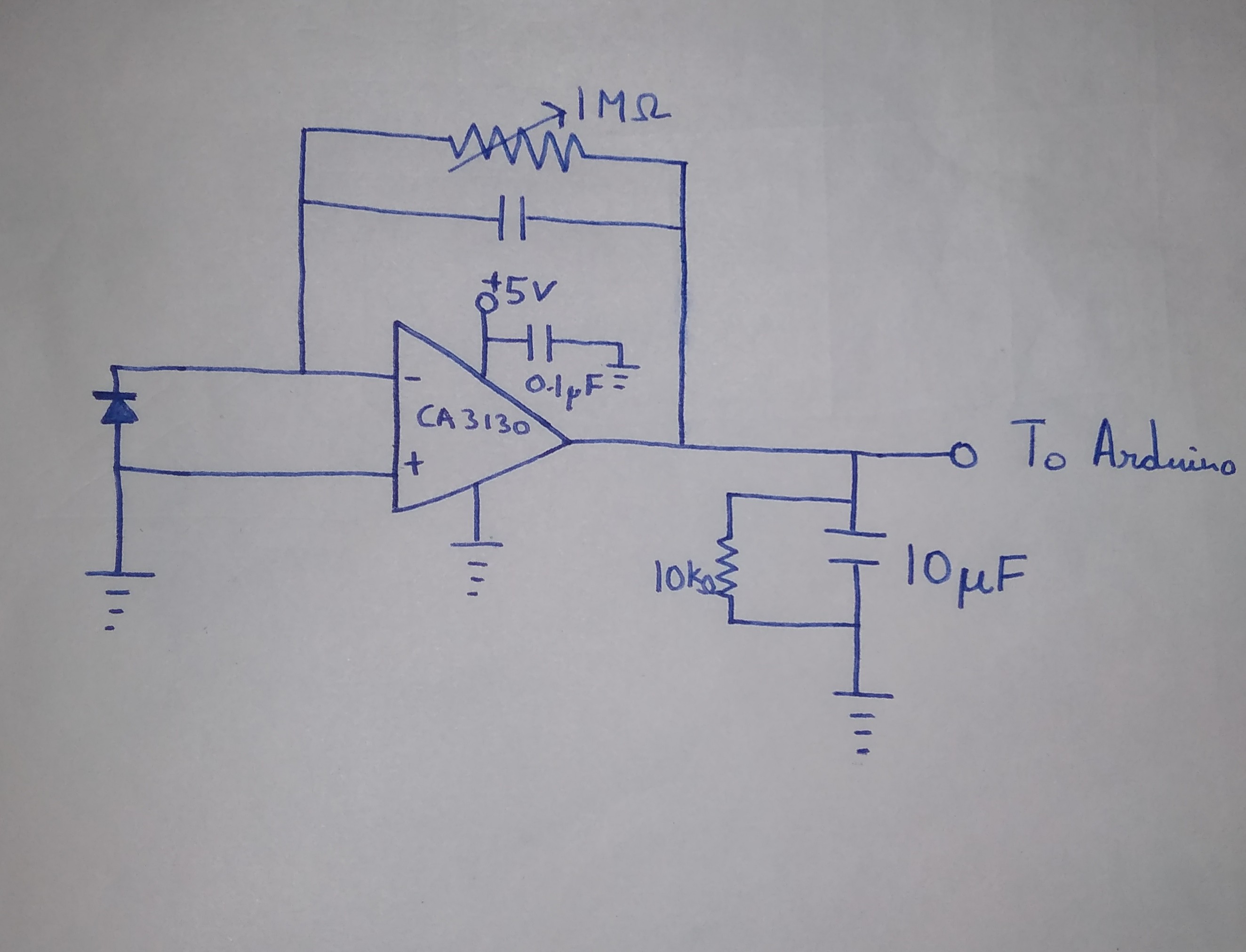
The output drives a capacitative load of 10 microfarads.
Here is what the circuit looks like.
![]()
λLab
A portable low-cost spectrophotometer for multiple parameter analysis of water quality