Close
0%
0%

Quarter-Century Lamp

Designing a battery-powered light to glow for 25 years

Similar projects worth following
I'm designing a light that will glow continuously for 25 years on a single battery (2 AA cells). This, of course, exposes a host of issues that I don't typically consider in my projects, so most of the work will be thinking through all the what-if's.

This is obviously a spin-off from TritiLED, but with different end-goals. The basic idea is the same, though: the technology in today's batteries (LiFeS2), ultra-efficient LEDs (InGaN), and low-power microcontrollers (PIC) enable LED markers with run-times measured in years or decades. Based primarily on the 20-year (95%) shelf-life of Energizer's lithium AA batteries, I've chosen 25 years as a design goal for this project.

I'm 47 years old as I write this. If these lamps actually run for 25 years, I'll be 72 when I can finally claim victory (maybe I should design a 50-year version instead). Just in case, I'll be giving one to each of my children so they can see if it worked.

A lot of the fundamental design for this project has already been done on #TritiLED - the basics of driving LEDs with peak efficiency pulses and aggressively sleeping the microcontroller to bring the current draw down to uA levels have been proven. What remains to be done is a thorough analysis of all the ways such a system could fail, and what can be done about it. I'm going to keep a table of all the identified failure modes here, and I'm asking for your help - when you think of anything I've missed, please comment and let me know! In the build logs, I'll discuss some of these issues and possible solutions. I'd ideally like to have a few units running by January 1, 2017.

I'm also going to have a look at the available NASA resources to see what advice they have on building ultra-reliable systems. If anyone has good links to this or other relevant information, please post them.

What Could Possibly Go Wrong?

It is exceedingly difficult to make predictions, particularly about the future.

- variously attributed to Niels Bohr, Yogi Berra, Samuel Goldwyn, Robert Storm Petersen, and Mark Twain

I'll be updating this table as issues are identified (entries are in no particular order):

Defect or Event

Impact

Mitigation

Identified By

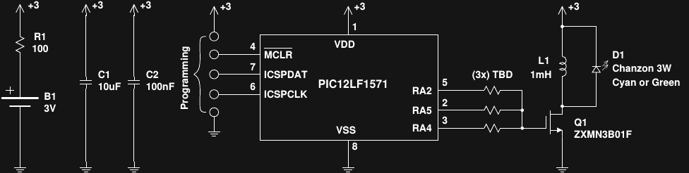
PIC12LF1571 flash program memory degradation Program gets corrupted, device fails Microchip used to specify 40-year program memory endurance, although I can't find it for this part. They also used to make the distinction between a "prototype" programmer and a "production" programmer - I need to research this. Probably OK (from @jaromir.sukuba see discussion) me
RAM corrupted by radiation Program hangs or malfunctions Periodically re-initialize all RAM from flash me
Battery vents, releasing high-pressure gas sealed case could rupture or explode provide vent holes or sacrificial vent in case me
Program hangs causing MOSFET to short battery across inductor Large current drain; inductor heats, causing burns or fire Include current-limiting resistors in battery connections (accept < 1% efficiency loss) me
Battery contacts / springs corrode Increased resistance to battery; possible failure Spot-weld battery contacts? Silver-epoxy battery connections? Battery doesn't have to be user-replaceable! me
Flux residue or contaminants (from handling) cause corrosion Device failure Thoroughly clean board after assembly, enclose in protective case me
Thermal cycling on board breaks SMD components Device failure Use vendor-approved pad layout and reflow solder profile. Consider using through-hole components - are they more rugged in this way? me
Rogue comet hits planet Life on Earth ceases Enjoy it while you can me
Component failure Device failure Burn-in all components to catch early failures. (Most) components are hugely de-rated in this circuit, which should greatly extend lifetime. me
PIC GPIO pins may exceed ratings on peak MOSFET gate drive current Early PIC degradation or failure Measure peak drive current to ensure it's within spec. Include gate drive resistor (at cost of circuit efficiency) if required. me
Post-assembly ESD event damages PIC or MOSFETs Device failure Enclose circuit to prevent direct contact with board me
ESD event during assembly Latent damage to PIC or MOSFET(s) reduce lifetime Use proper ESD protection in all phases of assembly me
Errant program behavior (unspecified cause) Device malfunction Code is periodically awakened by WDT; this should also break out of unintentional hung loops. The assumption is that the WDT has been designed to be robust. me
Environmental contaminants (inc. moisture) Corrosion or parasitic power drain Conformal coating on assembled board after thorough cleaning me

Portable Network Graphics (PNG) - 22.35 kB - 11/02/2016 at 17:51

Preview
Download

  • Warmup: 10-year "flashlight"

    Ted Yapo11/07/2016 at 19:38 0 comments

    I decided to throw this together to get some experience and think through some of the issues while I wait for parts to arrive. For a flashlight, it's pretty dim, but still useful. I can easily read with it once my eyes are dark-adapted. I expect it to run for about 10 years, just based on battery capacity and current drain. There is, of course, no power switch.

    Even though I don't trust 3D-printed materials to last 10 years (the QCL will use a metal case), I couldn't help throwing this into one. I used one of the #TritiLED V2.0 boards, a 1/4W 100-ohm resistor and a 2AA battery holder. I don't really trust a plastic battery case to last 10 years, either, but I had the stuff here, so I figured I'd throw together a prototype.

    I don't have the time to run a bunch of serial experiments if I might have to wait a decade or two to see if each one worked - the only thing I can do is try a bunch of stuff all in parallel.

    The circuit is essentially the one proposed in the last log, repeated here:


    The TritiLED V2.0 PCB I had available uses only two I/O's to drive the MOSFET gate, and doesn't have sites for gate resistors, so those were omitted. I modified the code to generate 6 LED pulses per wakeup, which put the current drain in the right ballpark, then tweaked the result by changing the OSCTUNE register to get the current right. with At the 3.6V nominal voltage from 2 LiFeS2 AA batteries, I measured 39.8 uA current drain. A simple estimate of the run-time divides the 3500 mAh capacity of the cells by the current drain:

    Of course, as the battery voltage drops (only slightly with this chemistry at these drain rates), the current consumption also decreases, extending the battery life somewhat. If everything goes according to plan, it will run for a decade.

    The assembly-language code is shown at the end of this log. The basic loop is driven by the watchdog timer, waking the PIC every 16ms to output six sawtooth LED current pulses near the peak efficiency point for the LED.

    I don't know about the reliability of the WDT, and whether I can trust it to wake the part consistently for 10 years (1.97 x 10^10 times). On one hand, 20 billion times seems like a lot, but then again, the CPU in my desktop executes 20 billion instructions every few seconds. It just sounds different spread out over a number of years - but what to do? I've been thinking of external watchdogs, but then how do you ensure they don't reduce reliability? A malfunctioning watchdog could hold the PIC in continuous reset. I'll be devoting a log to the issue shortly. There don't seem to be any easy answers.

    A defensive feature of the code is to reset the PIC with a software reset instruction every 256 wake-ups (4.096 seconds). This should reset any RAM values that get randomly corrupted. Finally, the entire unused program space is filled with reset instructions - if program execution somehow gets to one of those locations, the part gets reset. I'm still thinking of possible improvements to the code. As with this whole project - if you see other ways this could fail, please let me know. The more things I can consider now, the better the chance of meeting the ultimate goals.

    Here are some pictures of the build (printed in PLA). I'm going to print another case or two in ABS or PolyMax, which should be a little more durable. I'll probably wait until some LED lenses and reflectors I ordered arrive, though - it would be nice to narrow the beam on this thing a bit. I thought of adding some heat-shrink tubing around the battery case once they were installed, but thought that this might keep them from sliding inside the case if the plastic holder relaxes over time (especially the positive contact without the spring). I have some steel battery holders on order for the QCL build.

    Here's the finished product. I added a note in the battery compartment with today's date and the expected run-time. When I showed the light to my wife, it was the first thing she asked about - she's seen too many times...

    Read more »

  • First Circuit Ideas

    Ted Yapo11/03/2016 at 03:10 5 comments

    So, here's the first circuit idea; it's a modified version of the latest TritiLED design:

    The battery is a pair of Energizer L91 "1.5V" lithium cells, which are actually 1.7-1.8 V when very lightly loaded. R1 limits the battery current in case the PIC gets stuck for a while and holds Q1 in a conducting state. Without R1, the full battery voltage winds up across the coil, which has a DC resistance of a few ohms at most (exact inductor not chosen yet) - enough power to cause burns or ignition. With R1 in place, the current is limited to 3.6/100 = 36 mA, and the dissipated power (mostly in R1) is limited to 3.6^2/100 = 130 mW - a small resistor can dissipate this all day if needed. 100 ohms in the power supply wires sounds like an efficiency killer until you realize that the whole circuit will draw around 15 uA (exact value TBD). At 15 uA average current, the drop across R1 is 150 uV, for an efficiency loss of only 0.05%. Not bad for keeping the inductor from possibly catching fire. In practice, I might want to use a 47-ohm resistor in each of the battery leads for redundancy - although they usually fail open, so this might not be the best idea. Of course C1 keeps the reserve power needed for the LED current pulses so the pulses aren't reduced by the inclusion of R1. I might add some extra capacitance at C1, which is a ceramic capacitor - there's no place for electrolytics in this type of application.

    In the TritiLED circuit this is based on, two output pins are directly paralleled to provide more gate drive, and no gate resistor is used. This sounds OK unless the software goes awry (cosmic ray strike) and doesn't switch the two output lines at the same time - then, they "fight" outputting different levels, drawing lots of current, and possibly damaging the internal drivers. In this version, the outputs are again paralleled for greater drive, but each has its own resistor to mitigate problems if they somehow switch separately. Additionally, the resistors limit the peak current the drivers need to output, reducing stress on the PIC. The exact values are TBD.

    I have the particular MOSFET at Q1 since it's the one currently in the TritiLED design. I have previously built these circuits with low-Vce(sat) BJTs, but the MOSFETs are a little more efficient. Unfortunately, I haven't yet found comparable low-Vgs(th) MOSFETs in through-hole packages. I'm strongly considering doing the whole circuit on a through-hole PCB, because I see many references that claim through-hole is more durable. I don't particularly care about size (the batteries will dwarf the circuit, anyway) or cost (only building a few) so through-hole is probably a better bet. The biggest reason to avoid SMD, however, is my lack of a proper reflow oven. While reflowing boards on an electric skillet might be OK for prototypes, it's completely inappropriate and untested for high-reliability devices. On the other hand, I have soldered tens of thousands of through-hole connections, and am confident that my through-hole joints will not be an issue, especially if I inspect each one under the mircoscope. I will be using eutectic 63/37 leaded solder (tin whiskers are for cat robots).

    There's no mode switch like on the latest TritiLEDs - a mechanical switch is likely to fail (especially the crappy SMD ones), or conduct ESD or mechanical stress to the board. Maybe worst of all, the internal "weak" pullups on this part consume 80uA when shorted to ground. Weak pull-ups, my ass.

    I'm thinking about a die-cast powder-coated aluminum enclosure with a little machining to let the photons out. I love 3D printing as much as the next guy, but expecting some case I printed to last 25 years? Nah.

View all 2 project logs

Enjoy this project?

Share

Discussions

--Oz-- wrote 07/08/2021 at 19:44 point

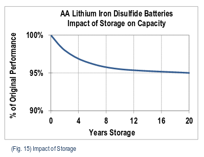
So the TritiLED does 5-10-or even 20 years(blinking) on a cr2032 235mA cell. You are saying your calculating ~25 years on two energiser lithium ultimate cells with 2900mAH. Of course there will be brightness difference, flashing freq/cont-on. What is the preformance difference between your circuit and the TritiLED (when yours is consuming ~10x the power)? TIA!  PS, still looking for a link to buy the pic your using to build one.

  Are you sure? yes | no

--Oz-- wrote 07/07/2021 at 23:09 point

I would think the first component to let go is the LED, the repetitive inductor kick without a current limit resistor "might" have a high'ish voltage (being clamped by the LED) or peak current. It would be interesting to remove the LED and see what the incutor kick voltage gets up to, then we know what the LED is seeing. Second component would be the FET (although the LED is absorbing the CEMF off the inductor, so should be OK, but I think it would go before the PIC. I was going to build one, where are you buying your PIC from (link)? TIA. EDIT: I put together the fet and 1mH ind, with 3V input, and a 10us pulse I am seeing +65V on the FET, clearly the FET is avalanching and clamping the CEMF voltage. In normal operation every pulse is beating the LED with high voltage, so I am pretty sure the LED would be the first to go.

  Are you sure? yes | no

David Fearon wrote 07/13/2018 at 08:33 point

Great project; just discovered this and your TritiLED work while researching for a similar sort of thing I'm working on.

One question: do you find the paralleled PIC outputs provide clean enough gate drive for the MOSFET? In the first iteration of my project (using ATMega 328P MCU) I'm using a v simple discrete gate drive with just a couple of transistors in push/pull totem pole configuration. I'd not considered paralleling outputs; I may try it to see how switching speed compares.

Thanks for the inspiration!

  Are you sure? yes | no

MarkRD wrote 07/06/2017 at 03:38 point

Ultra-low power stuff like this really geeks me out for some reason. Maybe it's the emphasis on finesse as opposed to MOAR POWAH!!! that can be seen in some other projects using excessive hardware.

I don't think you need to worry about the reliability difference between SMD and through hole. I used to work in the testing lab of Nexteer, a Tier 1 automotive supplier that makes electric power steering. Those boards were all SMD, and in the lab we put them through far more abuse than your circuit will ever see. Some of these boards were mounted on the steering rack, so we had to make sure they could survive humidity, temperature cycling, thermal shock, vibration, and mechanical shock.

I don't know if there's any special layout or soldering technique used for automotive stuff, but if SMD's good enough for steering I think it'll be good enough for your light. Unfortunately I can't offer you any inside knowledge since I was just a lab tech and not an engineer.

  Are you sure? yes | no

jaromir.sukuba wrote 11/02/2016 at 17:06 point

Regarding the 12LF1571 FLASH retention - it is there in datasheet http://ww1.microchip.com/downloads/en/DeviceDoc/40001723D.pdf on page 269, parameter D124, specified as 40 years typical - at standard operating conditions, ie. up to 85degC or 125degC respectively. I expect operating at room temperatures or lower than that (less than 30degC, say) will add one order of magnitude to this number.

Since the days when OTP made of EPROM cells are mostly forgotten, you don't need to distinguish between development (verification at single VDD voltage) and production programmer (verification at multiple VDD levels, because EPROM is just analog circuit, after all), programming specs. are the same. The only difference between programmers in FLASH days is perhaps the ruggedness.

  Are you sure? yes | no

Ted Yapo wrote 11/02/2016 at 18:02 point

Thanks!  I think they used to put the 40-year number right in the bullet points at the top of the sheet; I guess it's too crowded with peripherals up there now...

I'm going to assume fairly constant room-temperature operation (mostly for the battery's sake).  It's less of a practical light than a long-term experiment.

I was actually going to ask you about the devel/prod programmer distinction - I've been eyeing your programmer projects so that people wanting to build some of my stuff don't have to buy a PICkit.

  Are you sure? yes | no

Mangus Tiranus wrote 11/02/2016 at 16:45 point

Im not sure the batteries themselves would last 25 years... The chemicals inside them would dry up or corrode on their own long before they finish using up there available power... But this is a cool idea.

  Are you sure? yes | no

Ted Yapo wrote 11/02/2016 at 17:57 point

Based on all the problems I've had with carbon-zinc and alkaline cells over the years, I would tend to agree with you, except that LiFeS2 cells are a different beast entirely.  The datasheet:

http://data.energizer.com/PDFs/l91.pdf

specifies a 20-year shelf life (and I have a package of them on my desk with a 2036 date code).  Looking into it a bit more, Energizer's applications manual:

http://data.energizer.com/PDFs/lithiuml91l92_appman.pdf

shows about 95% remaining capacity at 20 years:

They used to specify 15 year shelf life, so they've either improved the design, collected better data, or have stretched the truth even more - who knows? They've been making these since 1989, so presumably they have enough data at this point to make decent estimates.  But of course, you never know how many marketeers vs engineers were involved in writing the datasheet.

In any case, I figured I could maybe assume 90% remaining capacity at the 20-year mark to be slightly conservative.  I could go all-out and use a 50% de-rating, but the light would be that much dimmer.

  Are you sure? yes | no

Similar Projects

Does this project spark your interest?

Become a member to follow this project and never miss any updates