 Ted Yapo
I decided to throw this together to get some experience and think through some of the issues while I wait for parts to arrive. For a flashlight, it's pretty dim, but still useful. I can easily read with it once my eyes are dark-adapted. I expect it to run for about 10 years, just based on battery capacity and current drain. There is, of course, no power switch.

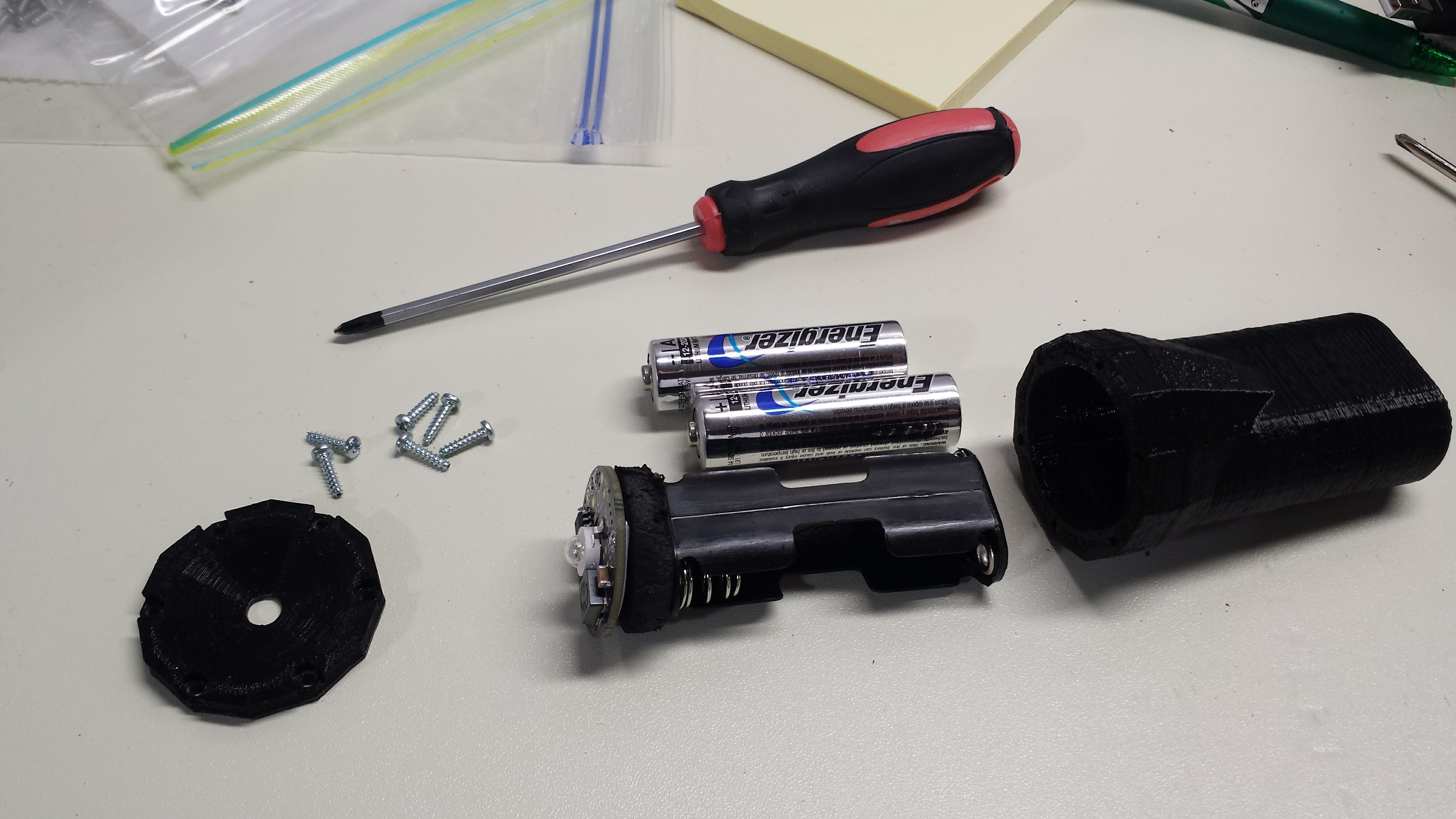
Even though I don't trust 3D-printed materials to last 10 years (the QCL will use a metal case), I couldn't help throwing this into one. I used one of the #TritiLED V2.0 boards, a 1/4W 100-ohm resistor and a 2AA battery holder. I don't really trust a plastic battery case to last 10 years, either, but I had the stuff here, so I figured I'd throw together a prototype.
I don't have the time to run a bunch of serial experiments if I might have to wait a decade or two to see if each one worked - the only thing I can do is try a bunch of stuff all in parallel.
The circuit is essentially the one proposed in the last log, repeated here:
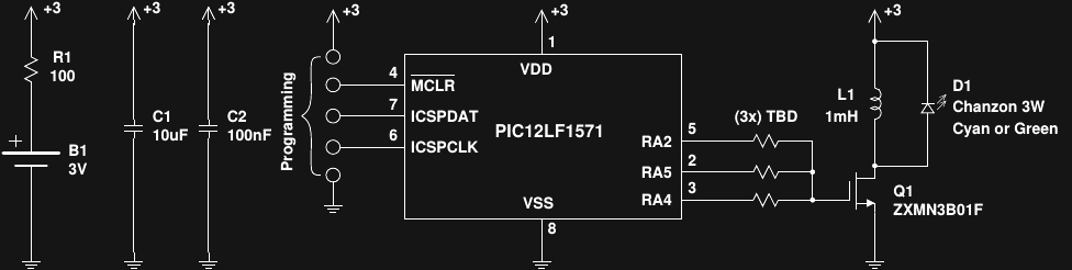
The TritiLED V2.0 PCB I had available uses only two I/O's to drive the MOSFET gate, and doesn't have sites for gate resistors, so those were omitted. I modified the code to generate 6 LED pulses per wakeup, which put the current drain in the right ballpark, then tweaked the result by changing the OSCTUNE register to get the current right. with At the 3.6V nominal voltage from 2 LiFeS2 AA batteries, I measured 39.8 uA current drain. A simple estimate of the run-time divides the 3500 mAh capacity of the cells by the current drain:
Of course, as the battery voltage drops (only slightly with this chemistry at these drain rates), the current consumption also decreases, extending the battery life somewhat. If everything goes according to plan, it will run for a decade.
The assembly-language code is shown at the end of this log. The basic loop is driven by the watchdog timer, waking the PIC every 16ms to output six sawtooth LED current pulses near the peak efficiency point for the LED.
I don't know about the reliability of the WDT, and whether I can trust it to wake the part consistently for 10 years (1.97 x 10^10 times). On one hand, 20 billion times seems like a lot, but then again, the CPU in my desktop executes 20 billion instructions every few seconds. It just sounds different spread out over a number of years - but what to do? I've been thinking of external watchdogs, but then how do you ensure they don't reduce reliability? A malfunctioning watchdog could hold the PIC in continuous reset. I'll be devoting a log to the issue shortly. There don't seem to be any easy answers.
A defensive feature of the code is to reset the PIC with a software reset instruction every 256 wake-ups (4.096 seconds). This should reset any RAM values that get randomly corrupted. Finally, the entire unused program space is filled with reset instructions - if program execution somehow gets to one of those locations, the part gets reset. I'm still thinking of possible improvements to the code. As with this whole project - if you see other ways this could fail, please let me know. The more things I can consider now, the better the chance of meeting the ultimate goals.
Here are some pictures of the build (printed in PLA). I'm going to print another case or two in ABS or PolyMax, which should be a little more durable. I'll probably wait until some LED lenses and reflectors I ordered arrive, though - it would be nice to narrow the beam on this thing a bit. I thought of adding some heat-shrink tubing around the battery case once they were installed, but thought that this might keep them from sliding inside the case if the plastic holder relaxes over time (especially the positive contact without the spring). I have some steel battery holders on order for the QCL build.
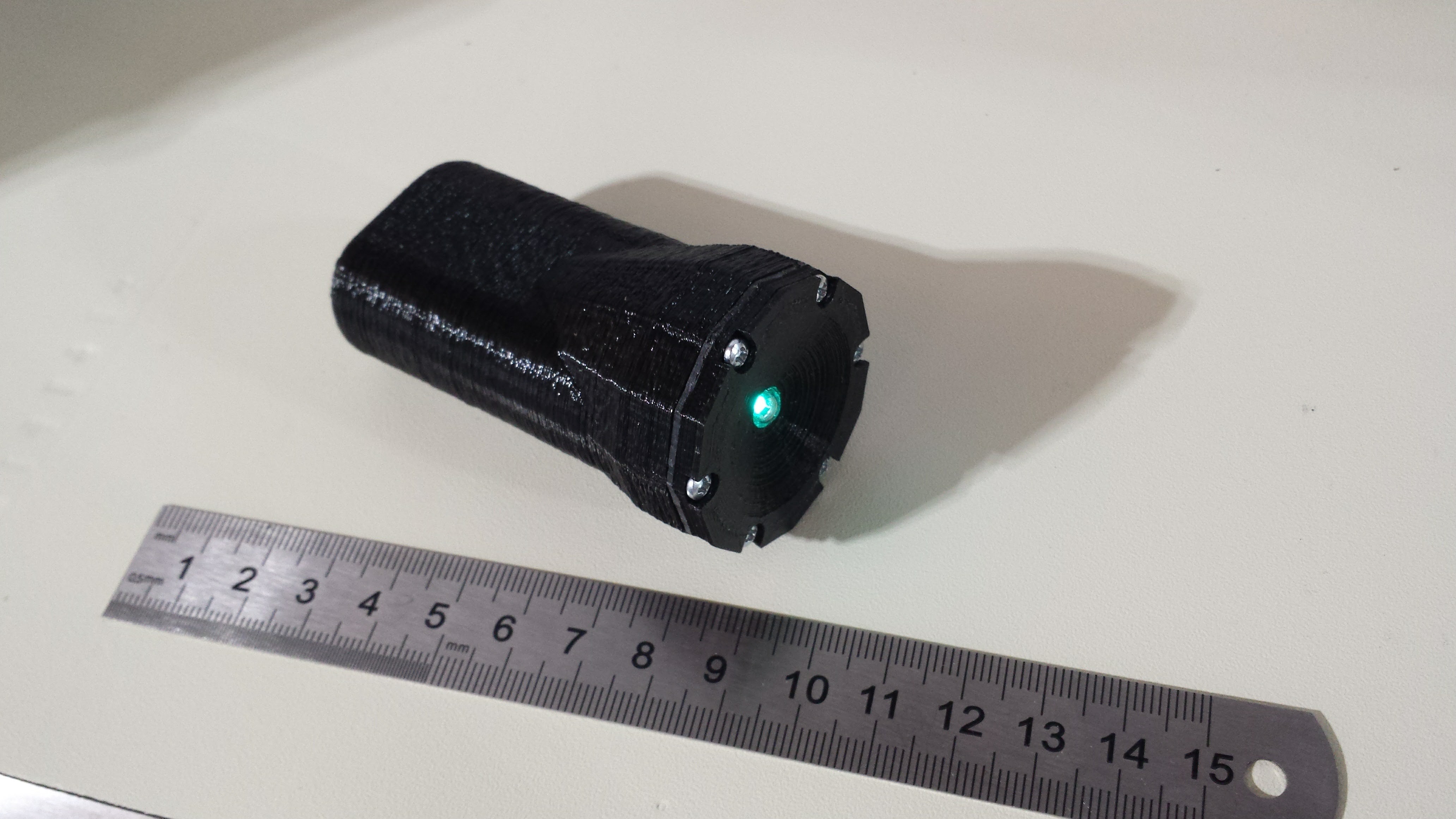
Here's the finished product. I added a note in the battery compartment with today's date and the expected run-time. When I showed the light to my wife, it was the first thing she asked about - she's seen too many times I wished I had dated some project from years ago.
Here's the code:
;;;
;;; ten_year_lamp.asm :
;;;    PIC12LF1571 code for (2x) LiFeS2 AA-powered LED glow marker
;;;
;;;  20161106 TCY

    LIST        P=12LF1571
 #include

  ERRORLEVEL -302
  ERRORLEVEL -305
  ERRORLEVEL -207

;;;
;;; OSCTUNE_VAL: set to fine-tune current draw for compensating for
;;;              component tolerances
;  OSCTUNE_VAL  equ   0
;  OSCTUNE_VAL  equ   b'00100000'
  OSCTUNE_VAL  equ   b'00011111'

;;;
;;; number of LED pulses per WDT timeout loop
;;;
  N_PULSES    equ   6

LED_PULSE   macro
  variable  i
  i = 0
  while i < N_PULSES - 1
  movwf     LATA              ;start inductor ramp-up
  clrf      LATA              ;end inductor ramp-up
  nop                         ; 2 nops here - tuned for minimum current
  nop
  i += 1
  endw
  movwf     LATA              ;start inductor ramp-up
  clrf      LATA              ;end inductor ramp-up
  endm

;;;
;;; I/O pin configuration
;;;
  GATE_DRIVE_A  equ   4
  GATE_DRIVE_B  equ   5

  __CONFIG  _CONFIG1, _FOSC_INTOSC & _WDTE_ON & _PWRTE_OFF & _MCLRE_OFF & _CP_OFF & _BOREN_OFF & _CLKOUTEN_OFF
  __CONFIG _CONFIG2, _WRT_OFF & _PLLEN_OFF & _STVREN_OFF & _BORV_HI & _LPBOREN_OFF & _LVP_ON

;;;
;;; variables in Common RAM (accessable from all banks)
;;;
  CBLOCK 0x70
    reset_counter
  ENDC

  ORG     0
RESET_VEC:
  nop
  nop
  nop
  nop
INTERRUPT_VEC:
  BANKSEL   OSCCON
  movlw     b'00111011'      ; 500 kHz MF osc
  movwf     OSCCON

  BANKSEL   OSCTUNE
  movlw     OSCTUNE_VAL
  movwf     OSCTUNE

  movlw     .255
  movwf     reset_counter

  BANKSEL   ANSELA
  movlw     b'00000000'     ; all digital I/O
  movwf     ANSELA

  BANKSEL   LATA
  clrf      LATA

  BANKSEL   TRISA
  clrf      TRISA           ; set all lines as outputs

  BANKSEL   WDTCON
  movlw     b'00001001'     ; WDT 16ms timeout
  movwf     WDTCON

  BANKSEL   LATA
  movlw     (1 << GATE_DRIVE_A) | (1 << GATE_DRIVE_B)

MAIN_LOOP:
  LED_PULSE
  sleep
  decfsz    reset_counter
  goto      MAIN_LOOP
  reset

  ;; fill remainder of program memory with reset instructions
  fill      (reset), 0x0400-$
  END
Discussions
Become a Hackaday.io Member
Create an account to leave a comment. Already have an account? Log In.