 Simon Wirz
Because I wasn't able to control the ptc element with the AC dimmer I've decided to continue the testing. This time I will test various fan speeds and measure the chamber temperature. The ptc element will run at 100% load.
Testing:
The test setup from the previous test (testlog from 20.10.2020) as a reminder. The only difference in this test will be the ac dimmer between the fan and the 230 mains voltage.

The test setup consist of a cardboard box (volume of 0.088m^3) with three 100K temp. sensors.
- Sensor T: Located at the top/back of the box, should be a hotspot (temperature rise)
- Sensor B: Centered in the middle of the box
- Sensor C: Attached to the housing of the heater fan
The exhaust opening is constant throughout the test. The log process remains the same (rampsboard and excel post processing).
Results/Experience:
I was able to show that it isn't necessary to control the heating element to then control the chamber temperature. For the sensor in the middle (sensor B) are the results:
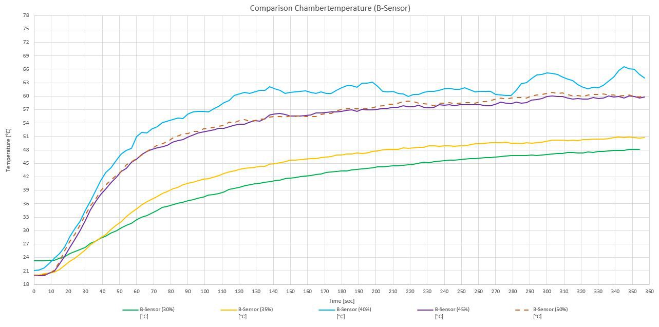
Like you would expect the temperature rises depending on the fan speed. But keep in mind that I've only tested for 6 minutes and the temperature (30%, 35%) does not seem to be stabilized. But it seems that the amount of air at the intake exeeds the amount of air at the outtake between 35% and 40% because of the delta T of 16°C (high temperature rise) and the suddenly flat gradient of the curve at 40%. The systems seems ''saturated'' at 40% because a further increase of the fan speed doesn't result in a higher chamber temperature.
For completeness the results of the housing temp (sensor C):
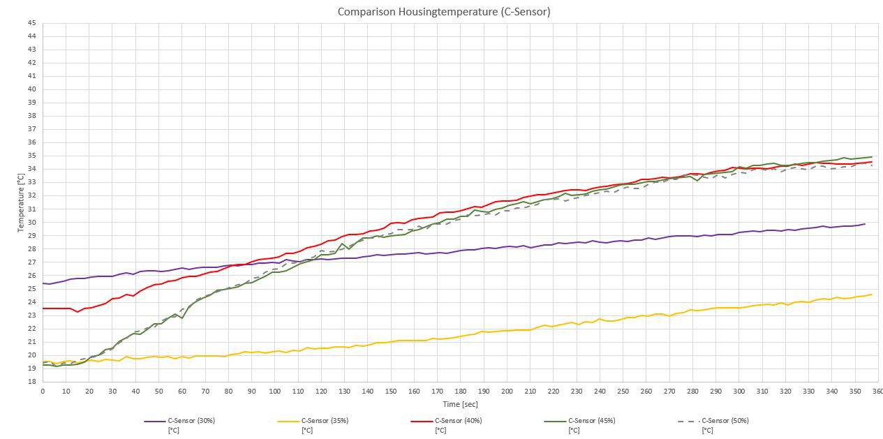
This graph shows the same behaviour. The intersection of the 30% and 35% is due to the different starting temperature. The gradient of the two curves are nearly the same.
Meaning for the Toolchanger:
WIP
Discussions
Become a Hackaday.io Member
Create an account to leave a comment. Already have an account? Log In.