 Simon Wirz
Next to the motion system all the auxillary components such as fans, airpumps and watercooling-system have to be connected and configured in the config.g of the Duet2Wifi.
The wiring illustrated:
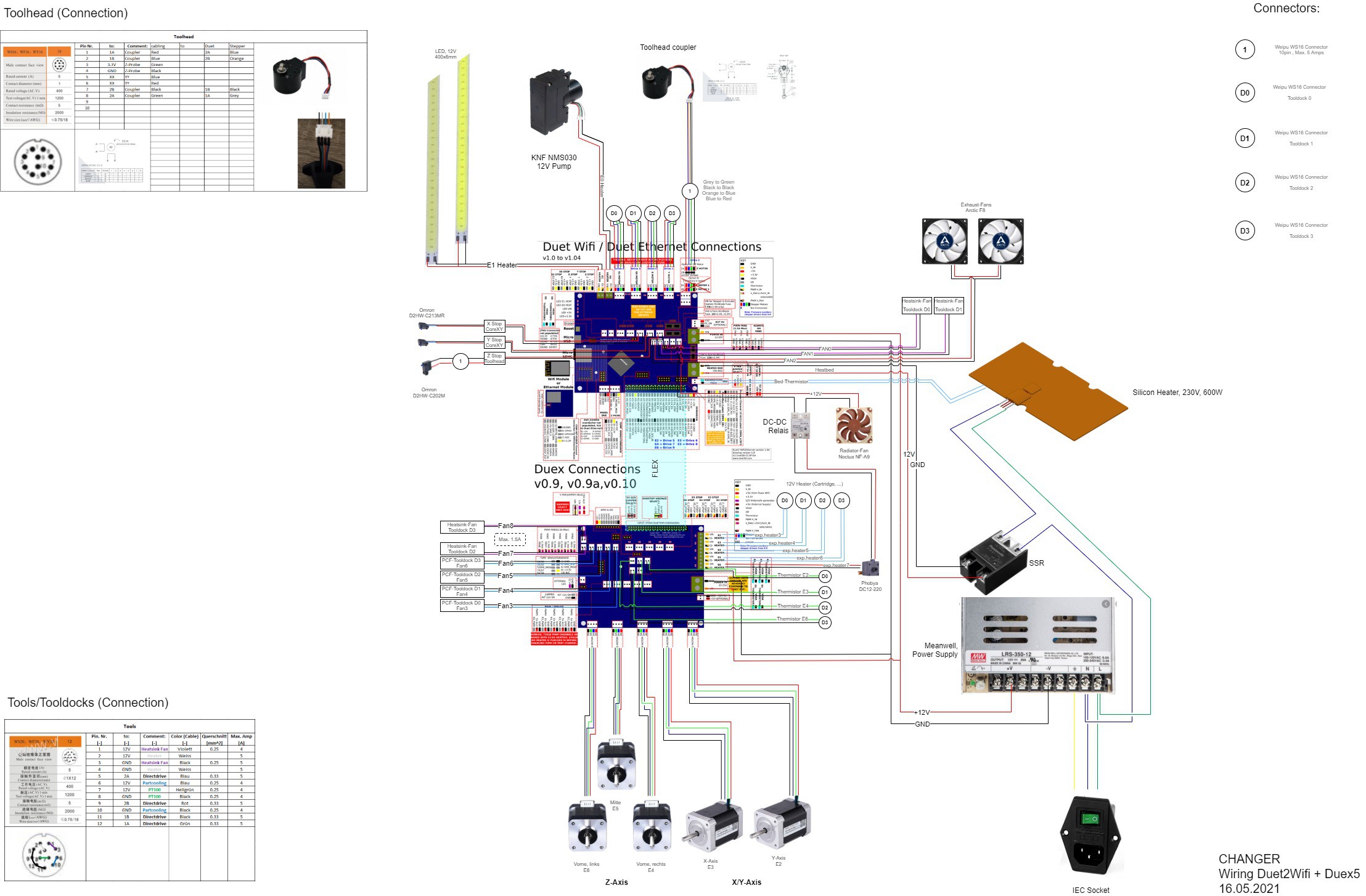
Because of the limited FAN and Heater-Outputs I had to control the radioator-fan of the watercooling loop with a SSR so the radiator switches on when the waterpump is switched on as well.
The fan configuration in config.g (RFF3...)
According to the ''wiring diagramm'' from above the configuration is the following:
M950 F0 C"e0heat" ; Air-Pump on E0-Heater-terminal
M950 F1 C"e1heat" ; LED-Light on E1-Heater-terminal
M950 F2 C"fan2" ; Exhaust-Fans (2 parallel) on Fan2
M950 F3 C"duex.fan3" ; Partcooling Fan Tooldock D0
M950 F4 C"duex.fan4" ; Partcooling Fan Tooldock D1
M950 F5 C"duex.fan5" ; Partcooling Fan Tooldock D2
M950 F6 C"duex.fan6" ; Partcooling Fan Tooldock D3
M950 F7 C"!exp.heater7" ; Watercooling-Pump on E6-Heater (Duex5)
M950 F8 C"fan0" ; Heatsink Fan Tooldock D0 on Fan0 (Duet2)
M950 F9 C"fan1" ; Heatsink Fan Tooldock D1 on Fan1 (Duet2)
M950 F10 C"duex.fan7" ; Heatsink Fan Tooldock D2 on Fan7 (Duex5)
M950 F11 C"duex.fan8" ; Heatsink Fan Tooldock D3 on Fan8 (Duex5)
M106 P0 S0 C"Airpump" ; Air-Pump
M106 P1 S0 C"LED" ; LED LIGHT
M106 P2 S0 C"Exhaust" ; Exhaust-Fans
M106 P3 S0 C"PCF-T0" ; Partcooling Fan Tooldock D0
M106 P4 S0 C"PCF-T1" ; Partcooling Fan Tooldock D1
M106 P5 S0 C"PCF-T2" ; Partcooling Fan Tooldock D2
M106 P6 S0 C"PCF-T3" ; Partcooling Fan Tooldock D3
M106 P7 S0 C"Waterpump" ; Watercooling-Pump
M106 P8 S0 C"Heatsink D0"
M106 P9 S0 C"Heatsink D1"
M106 P10 S0 C"Heatsink D2"
M106 P11 S0 C"Heatsink D3"
Versatility
The shown configuration section was just for initial testing and won't be like this in the end. We're working currently on a software concept to use the RFID-Chips to write and adapt the config.g file so the printer basically configures itself according to the tools on the CHANGER. In the near future if you insert a direct drive tool the E steps, driver current etc. are set automatically in the config.g file.
With this said the pins doesn't need to adress a heatsink fan or a partcooling fan in the end. It could be anything controllable with 12V.
Discussions
Become a Hackaday.io Member
Create an account to leave a comment. Already have an account? Log In.