 Simon Wirz
I'd like to print high temperature materials like PEKK, PEEK. Therefore I've implemented a watercooling system to keep the hotend cold which also allows the printer enclosure to be heated. I've searched a long time for a professional solution. I've found some compact heater fans which are used to heat control cabinets. STEGO Elektrotechnik GmbH offers some high quality heater fans in different options.
The CS028 Series:

I've decided to test the STEGO CS028, 400W, 230V Version and MURRPLASTIK AG Schweiz kindly sent me one to support this project. This heater uses a PTC-Element and therefore it is quite a safe way to heat your chamber. When the temperature rises the resistance increases as well and therefore the current decreases. With this configuration you'll have a safe thermal runout protection. On the other hand you have the disadvantage of a high switching current at lower temps (remember the ptc-element). An active control of the heating temperature could be difficult because of the fast on/off-switches. This heater fan also includes a integrated heater fan (230V) which (right now) is directly wired to the heating element and therefore can't be controlled in speed. So the only simple way to control the temperature in the heating chamber is to controll the exhaust airflow.
Testing:

The test setup consist of a cardboard box (volume of 0.088m^3) with three 100K temp. sensors.
- Sensor T: Located at the top/back of the box, should be a hotspot (temperature rise)
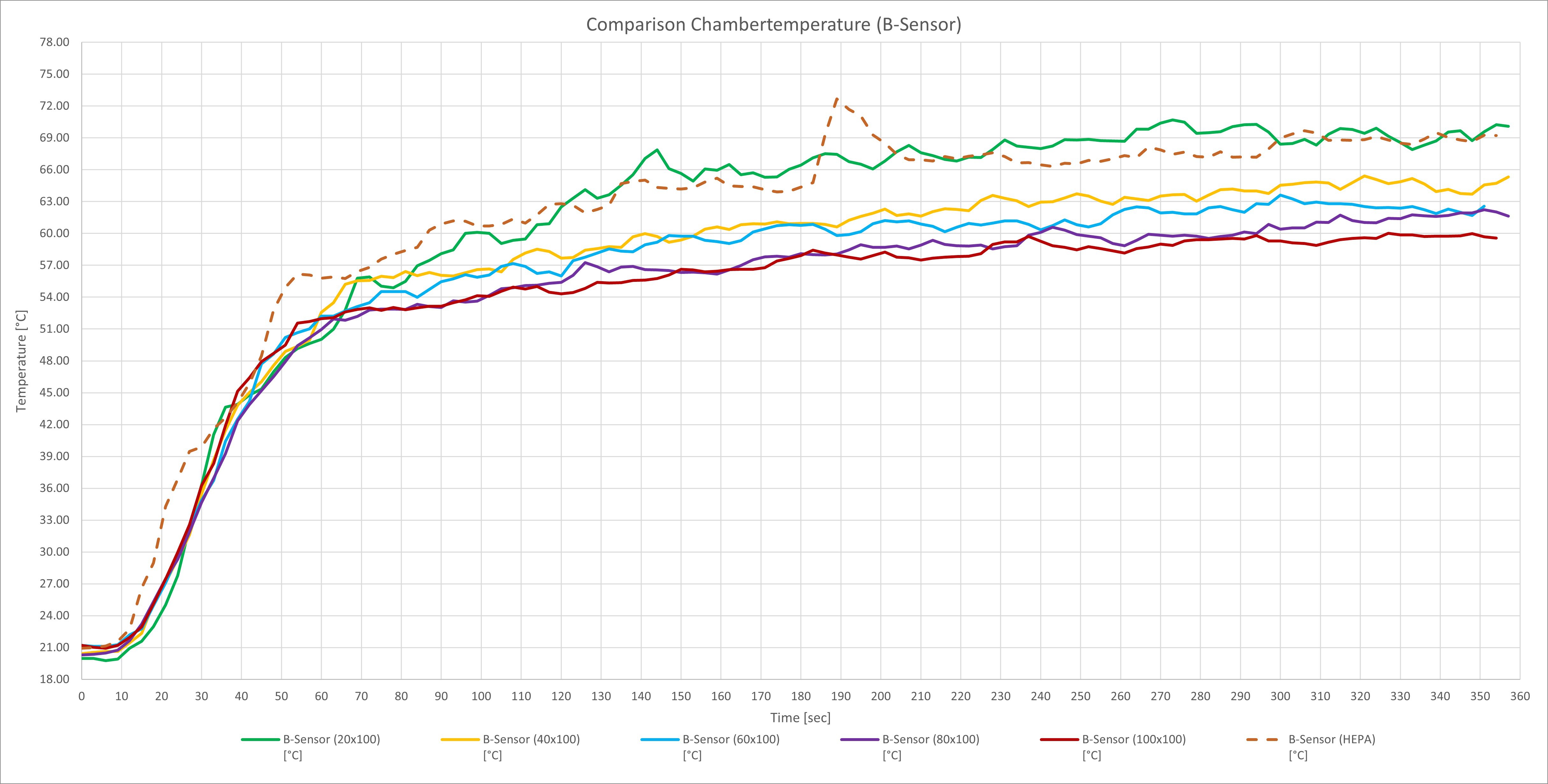
- Sensor B: Centered in the middle of the box
- Sensor C: Attached to the housing of the heater fan
To simulate various exhaust airflows I've cut a rectangle with 20mmx100mm, 40x100mm, 60x100mm, 80x100mm, 100x100mm in the top plate of the cardboard. I've started with 20x100 and increased step by step. I even used a HEPA-Filter (the one used in the roomba cleaners) but without a fan attached to suck the air out (I feared a backlog but tried it anyway)
For sensing the temperature I've used a Rampsboard with an Arduino Mega and configured Marlin 1.19 with an additional temperature input (heated_chamber). For logging I've used Pronterface. If you click on ''debug communications'' you'll get approx. all 3 seconds a status report which looks like:
RECV: ok T:20.16 /0.00 B:19.96 /0.00 C:20.27 /0.00 @:0 B@:0
SENT: M105
RECV: ok T:20.00 /0.00 B:19.96 /0.00 C:20.16 /0.00 @:0 B@:0
For filtering this message I than used excel to get the T:XX , B:XX, C:XX in seperate rows to finally plot the results and make some calculations (time to reach 60°C, max. deviation between Sensor T and B etc.).
The results/experience:
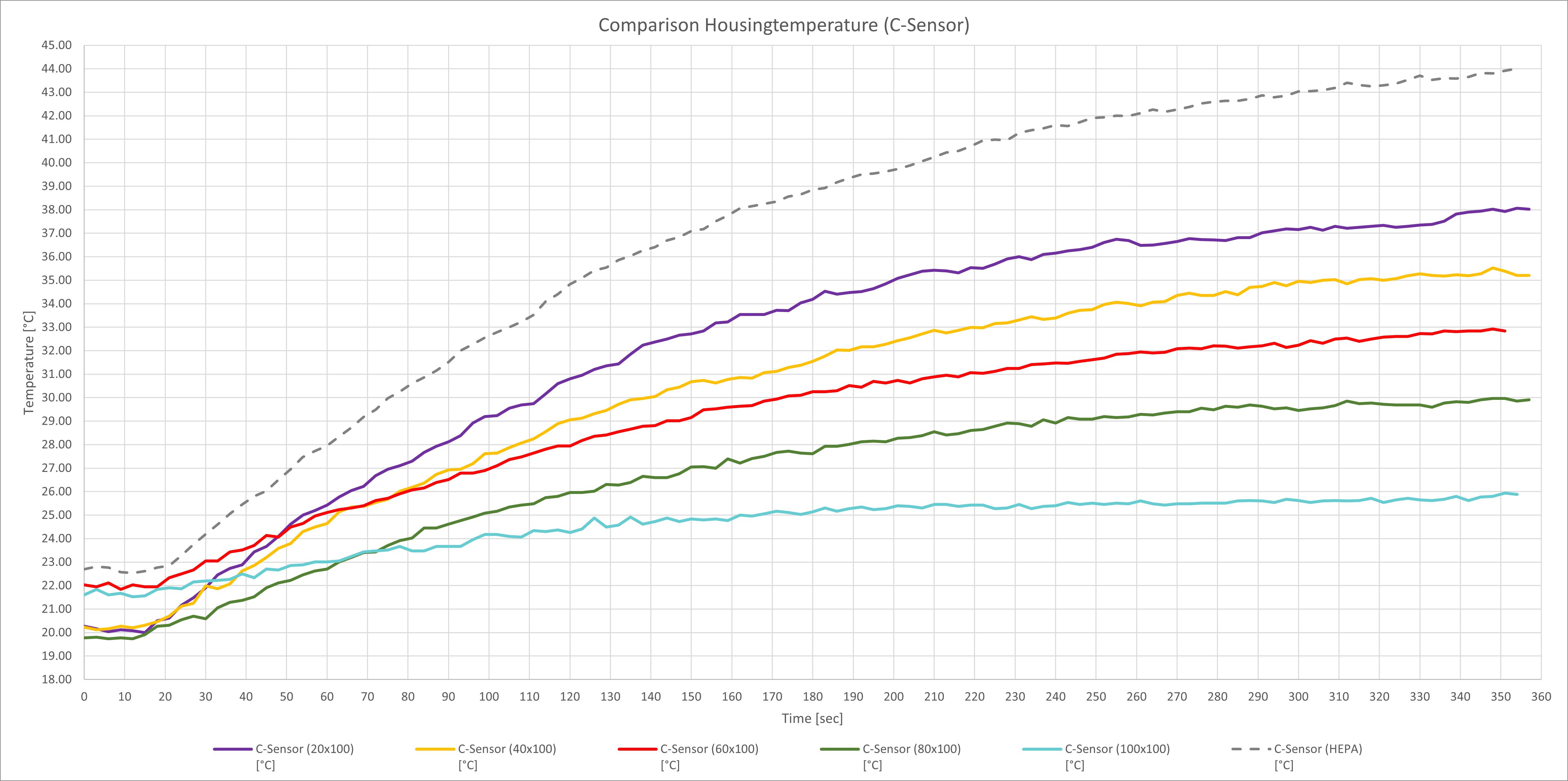
The results show what you would expect i've youre going to increase the exhaust airflow. The max. temperature decreases and it takes longer to heat up your ''chamber''. What's intresting you see that the HEPA-Filter and an opening of just 20mmx100mm almost results in the same behaviour. If you looking at the housing temperatures you'll see a correlation between exhaust airflow and housing temperature of the heater fan. As feared the HEPA-filter without a fan causes a heavy backlog which results in a higher temperature rise of the heater unit. Same goes for a high exhaust airflow. If youre letting a lot of the air out without any backlog the heater unit hardly gets warm. This comes at a cost of the max. chamber temperature (which is logical).
I did some measurements.
Time to reach 60°C with sensor B (middle of the box):
- 20x100mm: 96 seconds
- 40x100mm: 162 seconds
- 60x100mm: 168 seconds
- 80x100mm: 240 seconds
- 100x100mm: 327 seconds
- Hepa-Filter: 87 seconds
Max. reached temperature with sensor B
- 20x100mm: 70°C
- 40x100mm: 65°C
- 60x100mm: 63.5°C
- 80x100mm: 62°C
- 100x100mm: 60°C
- Hepa-Filter: 73°C (peak at 190seconds, caution)
Conclusion:
The tested heater unit is high quality made and can be used to quickly heat up a chamber with a volume of 0.09m^3. Because of the mentioned switching problems (high current peaks) the temperature can be controlled over the exhaust airflow BUT this comes at a cost of max. temperature. The heater unit is limited by design to a max. temperature and can't get any hotter ( I believe 80°C). If I want to reach a higher temperature I have to limit the exhaust airflow to a minimum this means the current design of the printer needs insulation and sealings at the door which contradicts my design philosophy of the printer. For the next step I'd like to test the heater unit with actively control the fan speed at a defined exhaust opening.
Discussions
Become a Hackaday.io Member
Create an account to leave a comment. Already have an account? Log In.