 Simon Wirz
Because I'm not a big fan of sensorless homing I implemented mechanical endstops for the x and y axis right from the beginning. The y-axis endstop is directly implemented in the idler-belt-tensioner and therefore in the same plane of the xy-motion system. The x-axis however was screwed to the extrusion of the frame what I never really liked because of the interface and the added error possibility when the coreXY-plate is removed and assembled again.
The old x-endstop:
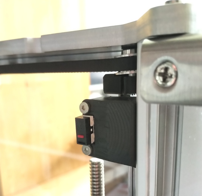
I also didn't like the way it looked with the large fdm-part and the micro switch clearly visible from all sides.
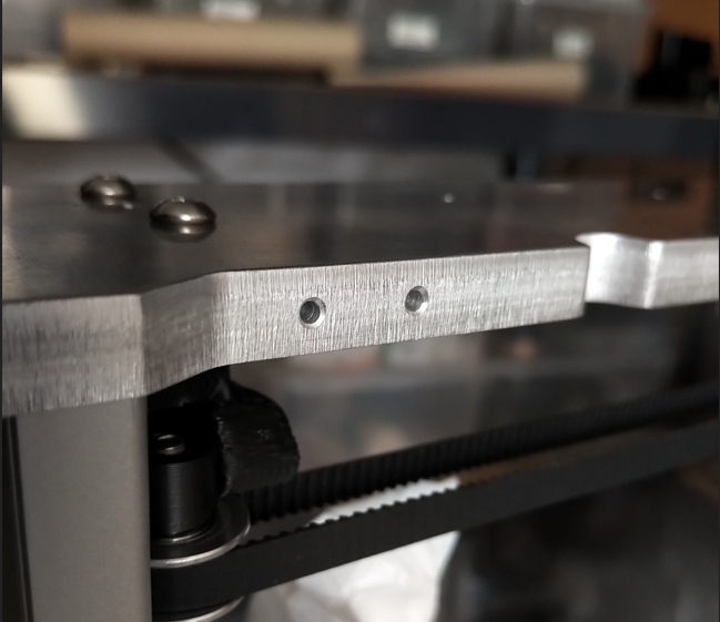
The new endstop:
For the new endstop design I had to drill two 2mm boreholes for two M2-threads.
After the taping I've installed the endstop holder (SLA-printed, printed on the Form 1+) with an OMRON switch installed. Because the new endstop is on the opposit side (x-direction) I had to rewire the endstop cable and re-configure the Duet firmware.
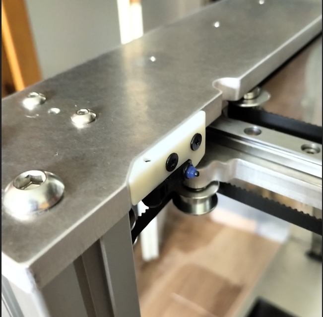
Now I can easily disconnect the endstop and take off the coreXY-plate without worrying about re-calibration or re-checking the position of the toolhead relative to the printbed.
Discussions
Become a Hackaday.io Member
Create an account to leave a comment. Already have an account? Log In.