Introduction/Summary
The primary design consideration taken into account was the robot not moving once locked. In retrospection, taking into consideration other teams' incredibly simple designs this was an err. The deadbolt lock mechanism proved effective when it was carefully aligned; however, carefully aligning the robot via remote control is easier said than done.


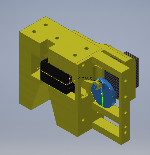
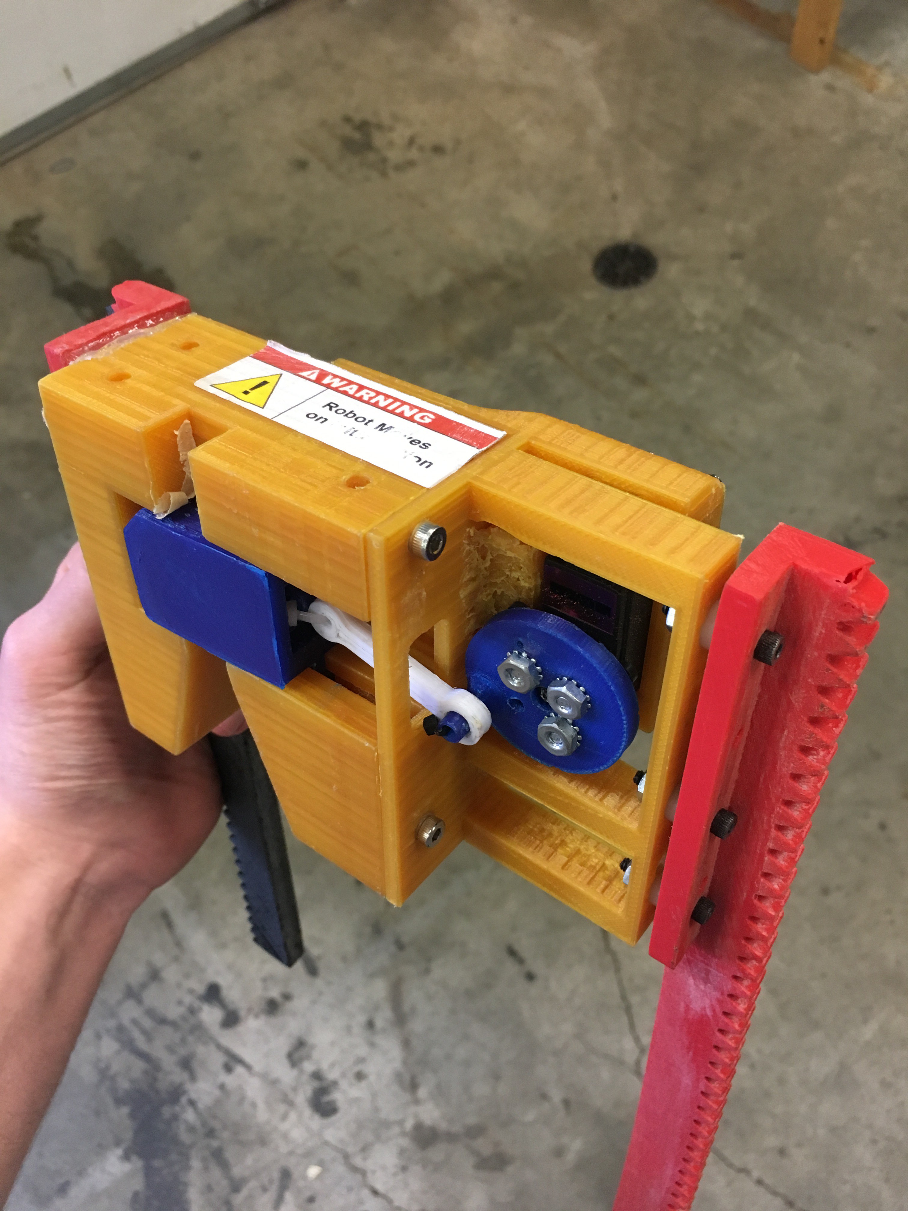
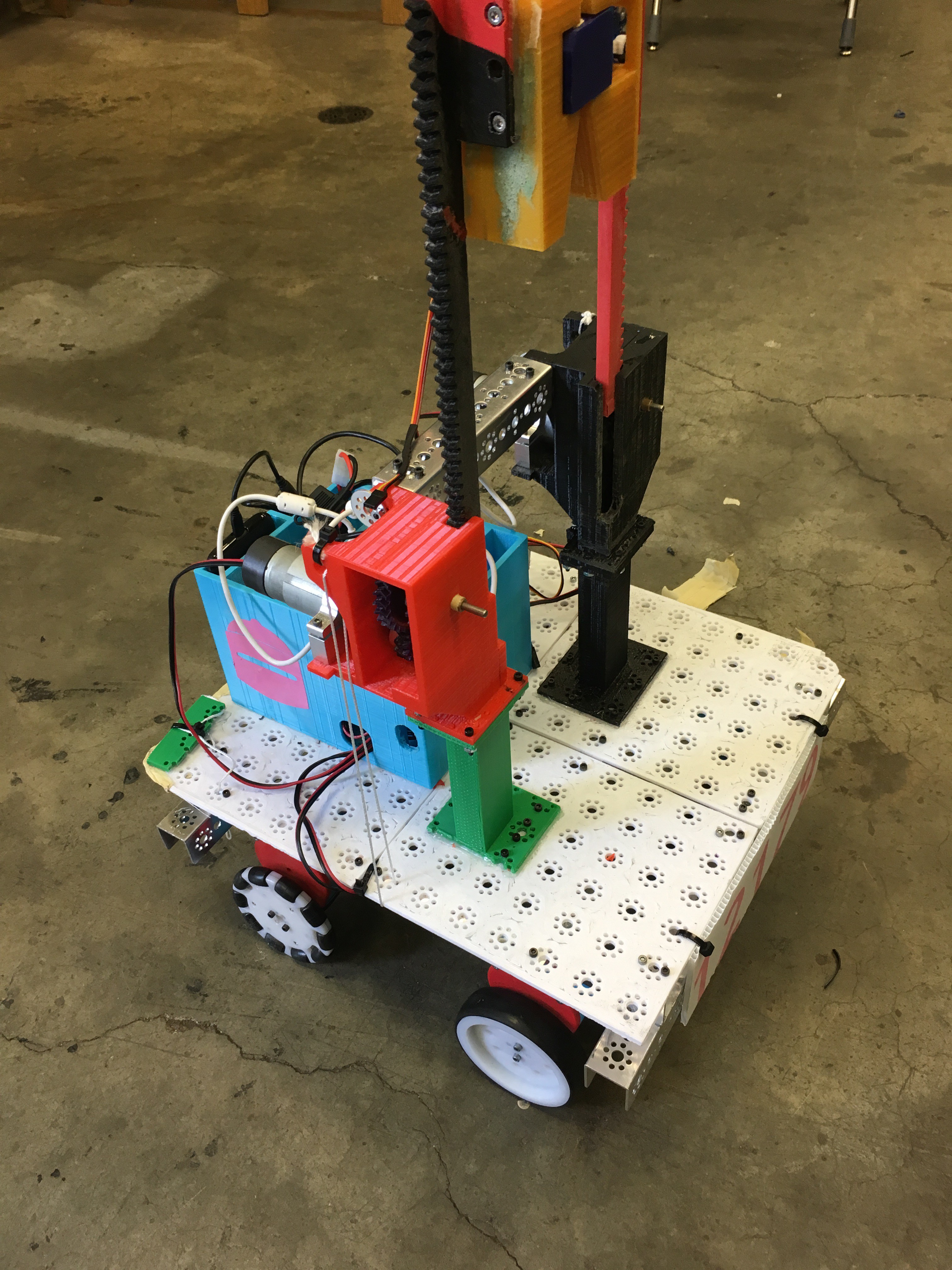
The body was designed in two pieces, which screw together via threaded-brass inserts. The 2 part design allows the deadbolt to slide within the grooves of the first body piece while being limited by the second. The desired operation is as follows: The driver of the robot raises the lock mechanism. They align the funnel below the deadbolt with the handle on the lander. The drive forward and lower the mechanism. Finally, the deadbolt is closed attaching the robot to the lander, which can then lift itself up. The deadbolt is slid open and closed via a hobby servo. The rotating motion of the servo translates into linear motion of the deadbolt via the connecting-arm which pivots on each end where it is attached.
Pros/Cons
The mechanism is assembled of many smaller parts, which makes replacing parts (because of design update(s) or break(s)) easier and less time-consuming. The design looks cool. However, as the designer, the issues far overshadow anything it does well. First, one of the integral issues is that lining up the mechanism with the handle proved incredibly difficult. Second, the servo means that a set of wires are hanging off the back of the mechanism--increasing the number of things that can go wrong (not to mention the extra slack needed for when the lock is raised). Both of the previous issues could be solved with a simplified, purely mechanical design. Finally, the deadbolt, which slides in an extruded dove-tailed grove (right side of photo above--one can see the lower groove below the white connecting-arm), had an issue where the front of it (left in photos) would "pop" out of the mechanism's body; this was because only the back of the deadbolt was anchored. To fix this, I would implement a catching feature, meaning the front of the deadbolt is funneled into a groove in the main body piece as it spans the lander-handle-gap.
 Silas Waxter
Discussions
Become a Hackaday.io Member
Create an account to leave a comment. Already have an account? Log In.