 Silas Waxter
User Experience (UX)
Check out the Device Description to understand what the device is supposed to do; the user experience is the intuitiveness and efficiency of the device's features. These are the targets:
- Manage Device Connections
- Report Raw Data (Quaternions)
- Select Rotation Type (i.e. flexion, extension, etc.)
- Select Body Region (i.e. wrist, knee, etc.)
- Record each repetition of motion (defined as the movement between resting point and maximum point of flexibility)
- Easily add repetitions or rotation types for a given region
- "New, Open, Save, Save As, Export..." features
- Used at the start and end of a rotation session
- "Settings" features
- Allows the user to change default settings about the application
- "Help" feature
- Points user to resources on how to use application
Device Topology
Preface
My goal is to turn this device into an actual product and to form a business around it. Looking for an investor intimidated me, so I limited myself to a couple of thousand dollars I'd saved over the years. I also am a novice at hardware design. For this reason, professional manufacturing (i.e. working with a board house, assembler, and product manufacturer) seemed out of reach. This drove me to search for small development boards that could be placed into the final product via headers. Therefore the only manufacturing I would have done would be PCB production for the simple PCB that'd connect the various components.
I now (10/28/20) realize this is ridiculous. It drove me to make unnecessary compromises (see ESP-Now below). Low-production runs are a thing, even if the price per unit is higher. Professional manufacturing allows a higher level of quality assurance and smaller footprints.
Switch to D1-Mini (ESP8266 Dev. Board)
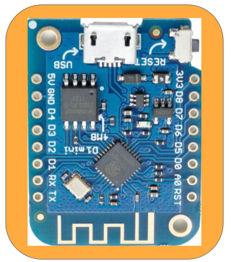
Driven by the search for a smaller development board and a low power communication method (was using std. Bluetooth), I changed microcontrollers to the D1-Mini, a board based on the ESP8266. This change also facilitated wireless sensor modules.
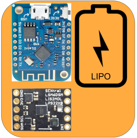
The ESP8266 is the younger brother of the ESP32; however, unlike the ESP32, there is no Bluetooth support--just wifi. Espressif, the creators of the ESP32 and ESP8266, created a protocol called ESP-Now, which according to their website, "...enables multiple devices to communicate with one another without using Wi-Fi. The protocol is similar to the low-power 2.4GHz wireless connectivity that is often deployed in wireless mouses. So, the pairing between devices is needed before their communication. After the pairing is done, the connection is safe and peer-to-peer, with no handshake being required."
By switching microcontrollers, the device topology and network topology changed.
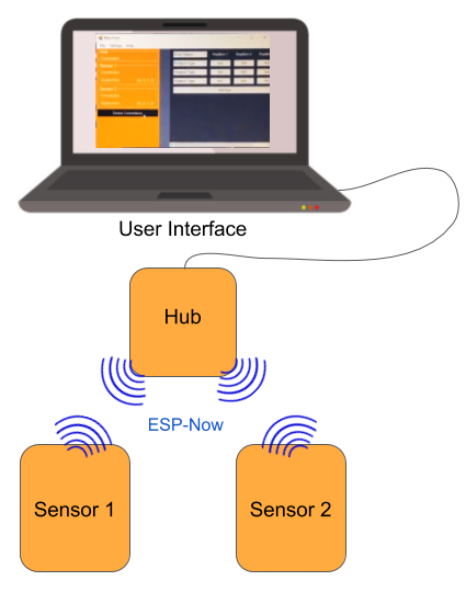
The most notable change is the change in connection. Now, each sensor is independent and wireless. Also important is the addition of the Hub module. This module acts as the translator between UI commands and ESP-Now communication.
The plan was for the Hub to be a development board with perhaps some LEDs and buttons. The hub is powered through the USB cable connected to the UI-device. Communication is also through this cable.
Connection Process
There are two steps to the connection process: Frist, the one-time distribution of information to each party. Second, the ESP-Now wireless connection that occurs at the start of each time the system is used.
The one-time distribution of information is one-time because the information shared is stored permanently on each device (the sensors, hub, and UI). This information consists of the device types, the mac addresses, and the AES128 key. Each sensor needs to know the mac-address of the hub module, and the hub needs to know the mac-address of each sensor. Additionally, the AES128 (Advanced Encryption Standard 128-bit [symmetric, one-key encryption]) key is initially generated on the UI and shared with each party. I realize storing the data on each device is a security pitfall, which is being addressed in the next iteration of the project.
The wireless connection which occurs every time the system is turned on occurs automatically if the one-time sharing of information has been distributed to all parties within the network.
Custom Command Interface
The connection process uses serial communication via the D1 Mini's onboard USB-Serial Converter (CH340G). A custom master-slave command interface was designed, where all commands and responses begin with "~" and end with "~\n". The UI is the master and the modules are the slaves. Below describes how this interface aided in the connection process:
Step 1: Device Identification
At the start of the connection process, the UI would scan for a list of com ports. It would then filter out those that do not possess the corresponding VID and PID (Vendor ID and Product ID). The UI would then issue the Initialize Serial Communication command:
//Command
~ISC~\n

//Possible Responses
~Sensor;macAdd[1:2:3:4:5:6]~\n
~Hub;macAdd[1:2:3:4:5:6]~\n
After the UI receives the response, it updates the device object by modifying the macAdd parameter. The UI then creates a new module-specific object: Hub, Sensor1, or Sensor2.
Step 2: Information Distribution
The aes128 key is shared with the device through the following commands:
Handshake
//Command
~R2Rkey~\n

//Response
~R2Rkey~\n

Sharing
//Command
~v8y/B?E(H+MbQeTh~\n        //Example aes128 key

//Response (5 sec. timeout)
~v8y/B?E(H+MbQeTh~\n        //Example aes128 key
Once the key is shared, the macAddress(es) is shared. For sensor modules, the Hub's address is shared; for the hub, the sensors' addresses are shared. This is accomplished through the following command:
Handshake
//Command
~R2RMac~\n

//Response
~R2RMac~\n

Sharing
//Command
~5C:B5:F2:43:58:C0~\n        //Example mac address

//Response (5 sec. timeout)
~5C:B5:F2:43:58:C0~\n        //Example mac address
Both the aes128 key and the mac address(es) are stored on the D1's embedded EEPROM.
Step 3: Restart Device
At startup, the D1's firmware checks the EEPROM for stored aes128 key and mac address(es); Therefore, to commence ESP-Now connection between the hub and sensors, all modules must be restarted. This is accomplished with the following command:
//Command
~restart~\n

//Response
~restarting~\n
Additional Features
Limited Com Ports
If the device running the UI has limited com ports, the user can check a box allowing the initial pairing process to be completed with this constraint. This feature was never implemented in the backend, but the plan was for a window (form) to appear that would guide the user through the process of plugging in and removing the devices.
Although the guide was never created, the events for plugging and unplugging devices were implemented. Windows generates an event on a USB plug and unplug.
- When a plug-in event occurs, the UI's event handler identifies the device as a sensor or hub via the method in step 1 of the connection process (Device Identification). After device identification, a pop-up form (window) appears querying the user as to whether they want to ignore this new device or whether they want to replace the hub (only when the new device is a hub) or replace Sensor 1 or Sensor 2 (only when the new device is a sensor).
- When an unplug event occurs, the UI's event handler modifies the central record of the attached devices, which is used during the connection process.
Sensor Flip
Once the initial distribution of information has been completed, Sensor 1 and Sensor 2 can be flipped, meaning Sensor 1 becomes Sensor 2 and vice versa.
Quaternion Streaming
After the sensors are connected to the hub, quaternions are streamed to the UI over its serial com port. Each line contains a quaternion and sensor ID; when read by the UI, it's parsed and stored in the corresponding sensor object's quaternion parameter. It also updates the UI's text box containing the quaternion stream.
Selecting Rotation Type and Body Region
This feature was never fully developed as it is more of the UX (user experience), and the UX is based on the backend "business logic." Regardless, a dropdown menu populated with default options was added to the table. (In the future, default options will need to be derived from the American Medical Association Guide, which is the standard for range of motion testing). In this drop-down, the user can either choose a default option or type in a custom value.
Adding more rows to the table automatically adds another "Rotation Type" drop-down menu in the first column's cell.
Record each repetition of motion
This portion of the UI will compare the quaternion stream from Sensor 1 and Sensor 2, and return the difference between the at-rest angle and the maximum angle. The following video is a rough visual aid to illustrate a wrist flexion & extension range of motion test:
Note: video is inaccurate in beginning; flexion and extension range of motion exercises are performed from at rest to corresponding maximum motion.
My knowledge (as of 11/01/20) is limited on the implementation of the following: The timestamped stream of quaternions from the sensors should be stored in a dataset; it should then be separated into smaller datasets based on each reptition. For each quaternion pair (quaternions measured on sensor 1 and sensor 2 at the same time) an axis of rotation will be calculated. (This is based on the principle that between any two orientations, there is an axis of rotation that allows one orientation to be rotated to the other.) Next, an "average" axis of rotation will need to be created; the angle between the quaternions in each quaternion pair can be calculated using this axis. Using the derivative of angle with respect to time allows one to see the speed of rotation (e.g. degrees per second). Given that the patient pauses at the resting and maximum position, the angles at these locations can be determined (speed of rotation = approximately 0). From this point the angle between resting position and maximum position can be calculated.
It should be noted that variance between the average axis of rotation and the quaternion pair's axis of rotation needs to be calculated and displayed to the user. This informs the user about how well the patient is rotating along a single axis.
Testing of measuring the angle between sensors. This was recorded to show error/inaccuracy I was receiving to the sensor's developer
Issues: Scrapping the Code
Modularity & inheritance
There was growing code smells in both the UI code as well as the hub and sensor firmware. This part the nature of programming projects and part me learning while working. For example, in retrospection, inheritance within the UI's object-oriented C# code would have made it a lot cleaner and easier to follow.
Around the time I decided to scrap the code, I was introduced to TDD, test-driven development. At first, I was skeptical, but I now believe this may reduce the issues that accumulate while working, and when they do accumulate, TDD provides a test-suite to ensure that refactoring does not break other parts of the system. TDD is not an end-all solution, yet it forces the programmer to design code that is testable (therefore modular) as well as increase the robustness of the codebase. As of 11/17/20, the next step of this project is to teach myself TDD in embedded C by following James Greening's book.
API/Pairing Method
The ESP-Now protocol is clunky and poorly documented. Bluetooth Low Energy communication is much more popular, meaning more documentation and trouble-shooting resources. The project requirements can easily be addressed by BLE; inventing a protocol or adapting one not directly suited is a waste of development energy.
Many modern computers support BLE natively, but BLE capabilities can be added with an off-the-shelf USB dongle. This would eliminate the Hub device meaning two independent sensors would connect to the user's computer over BLE. For the sensor, there are many small, low-power solutions that have integrated antenna and software libraries with BLE protocol implemented; typically, these two aspects already have passed ECC (and other agencies) communication regulations.
Arduino-Based Limitations
The Arduino Framework is excellent for making quick prototypes and hobbyist electronics, but it starts to become limiting when more advanced concepts are needed. Some of these are:
- Inability to manage Linker Script
- no boot-loaders:
- over-the-air (OTA) firmware update
- no boot-loaders:
- Abstraction hides functionality.
- direct-memory-access (DMA) is a common peripheral that allows data to be transferred from memory to peripherals and vice versa without/minimal processor intervention.
- I doubt DMA is implemented underneath the hood in Arduino. It would depend on how the board support package developers mapped the Arduino Framework to the uC.
- No Debugging
- modern embedded development use in-circuit debugger/programmers such as ST-Link or J-Link probes; these allow the programmer to insert breakpoints, read, and write registers.
- Comparatively Terrible Integrated Development Environment (IDE)
- This doesn't affect the project quality directly, but the native Arduino IDE is terrible. It fails to include a file viewer, auto-completion, spell-checking, and all the other features common in contemporary IDEs.
Discussions
Become a Hackaday.io Member
Create an account to leave a comment. Already have an account? Log In.