 Rob Ward
The initial aim of this project was to not throw out my Robox printer as e-junk and try to recycle it. This will be an ongoing challenge to many environmentally committed 3-D printer enthusiasts. The Robox design had been brilliant, but as it aged I found it hard to justify paying for maintenance. High cost of spares and proprietry software. Undeniably it was a really good, but expensive, option to learn 3D printing on. It was pretty much a point and click system with so many good features it would take another article just to list them. I got a lot of use from it and learned heaps, but eventually parts wore out and there was no service any longer in Australia. Too expensive to ship to the UK for servicing. It had an ARM chip on the motherboard so CEL was selling 32Bit 3D printing right back in 2016. A very smooth system. I was emotionally attached, and could not just chuck it out. I knew I was risking money on an unproven (and no doubt uneconomical) project, but what I learned was invaluable.
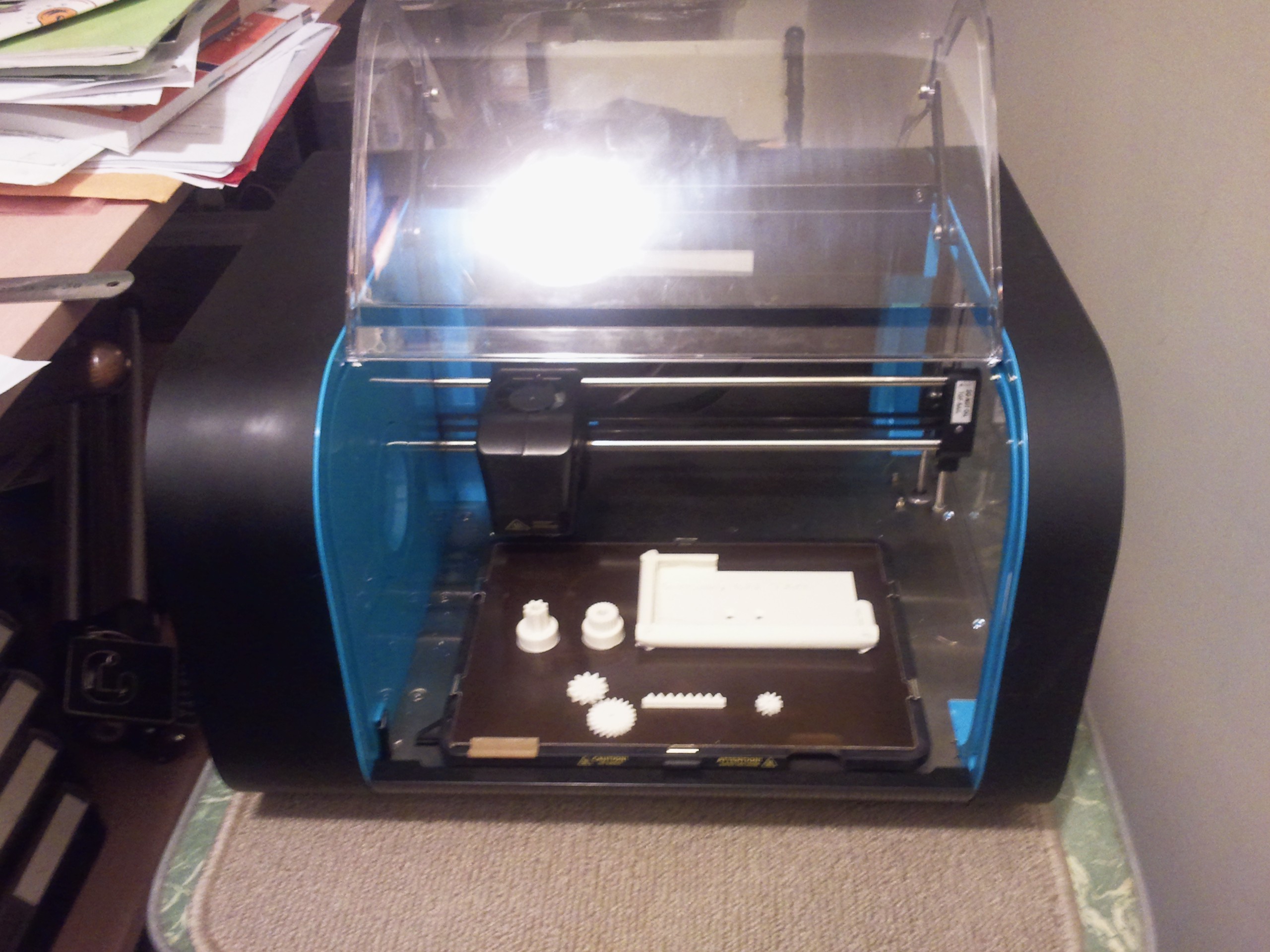
Above: The unmodified Robox, including filament wiper, fibre glass, removable adhesion board, nozzle sensing Z-Axis limit switch, automatic filament reel recognition, filament distance sensor, opposing gears on filament drive, heated chamber, easy filament load and unload and expandable to dual filament. Just to describe some, not all...
In the end I chose to gut the printer of the electronics, just keeping the case, the limit switches and the mechanical parts (motors, belts, rails etc). I was not at all hopeful when I began, and at first simply tried to discover how to drive the motors that controlled the system. I had a RAMPS 1.4 board and Mega2560 from another project, so I rigged up the XYZ motors to move them around. After some success I then traced the limit switches and figured out how to make use of them. This involved some considerable trace cutting and PCB hot wiring but allowed me to do a G28 using MARLIN. It was fun at this stage, but not particularly promising. The challenges looked like fun.
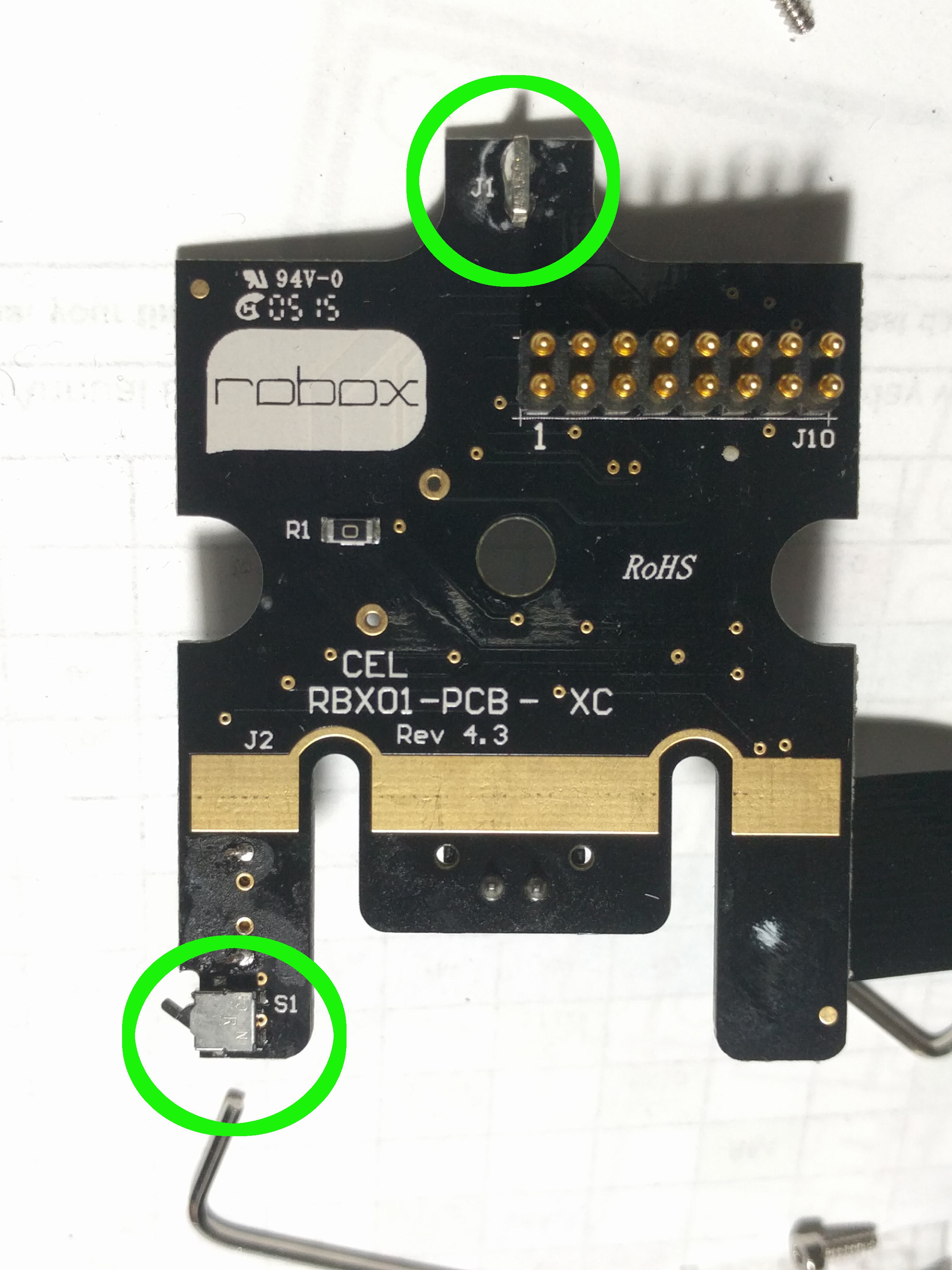
Above: This shows the Z-Axis limit switch that presses against the top rail and the X-Axis limit switch on the lower left. The tracks to these were isolated and "hotwired" out to the new mother board.
The next challenge was to test out the Bowden filament driver motor. (A nice design with a geared motor, opposing drive gears on the filament, filament detector, and an optical travel wheel.) Pushing filament proved easy, but the next part of the process was going to be the big challenge. I got a quick extruder calibration. A CR-10 hotend module was sourced off eBay along with a 12V 30A PS. The hot-end was an early design that eBay dealers were unloading and I mistakenly thought it was good value for the risk of the whole project probably being a lemon. I was able to adapt the fittings for the Bowden tube connection to be able to get the un-mounted hot-end extruding molten plastic. So far so good. A fairly unique feature of the Robox was the way the filament came into the original hot-end at the back and entered parallel to the build board. This was then heated and extruded downwards at right angles towards the build board. There was no way I was going to be able to mimic this straight off. I could mount a fan on the front of the print head to cool the filament feed.
Fortunately the Robox heads are interchangeable so I took it out, and apart, and cut a section off the heat sink and made a flat plane that I could screw the CR-10 hotend onto. The geometry of the nozzle from the X-Axis gantry was pretty close to the original and looked ok. The Robox setup has the Z-Axis limit switch acting on the rotation of the print head when it contacts the build board. So the nozzle itself becomes the "sensor tip" for the Z-Axis limit switch. This would prove to simplify some things but make others very much more complicated. With just a couple of 3mm bolts the new printhead was attached to the remains of the old printhead's heatsink. I could finally begin some test prints. I just accepted that the filament was going in vertically for the moment.
Above: This shows the CR10 hot-end screwed to the modified Robox heat sink, with the modified Bowden couplings feeding in. A more up to date Creality Print head would have been a much better choice.
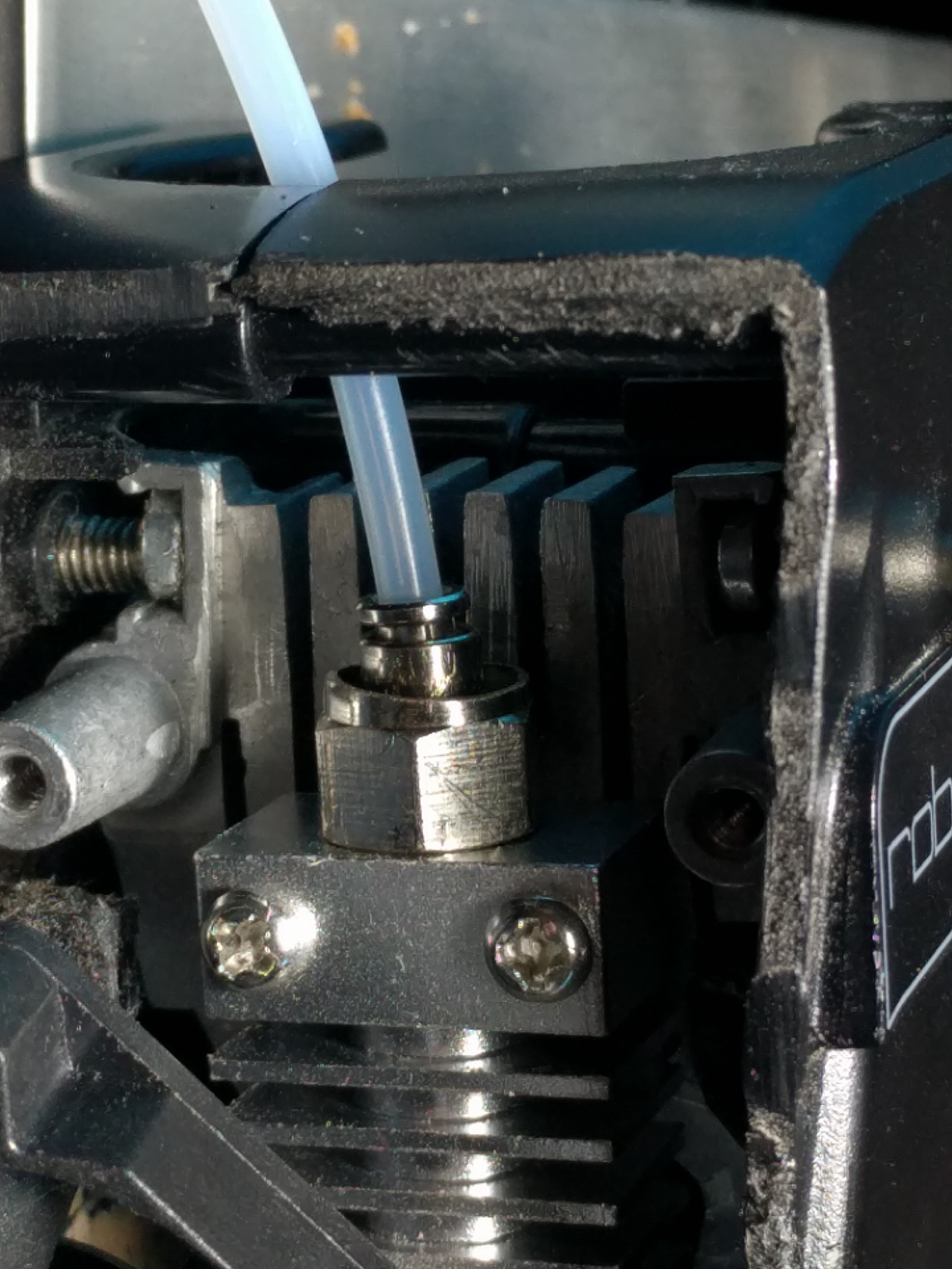
Above: The Bowden tube arrives vertically, and the throat is bolted to the angle Aluminium. The 35mm fan on the front made this an effective combination without heat sink fins. The large blue wedge was designed to screw onto the black backing plate (it carries the X and Z axis limit switches, just visible pressing on the top rail). Small fibre washers were placed between the PLA mounting wedge and the L heatsink to minmise heat transfer to the PLA.
The results were initially encouraging, but the feed to the printhead was very erratic and getting a consistent flow was a problem. There were many blockages and filament jams. In the end I discarded the CR-10 as a flawed design (NB I did buy a more recent CR-10 design as an option and it looked so much better, but I had moved on by the time it arrived) as it had too many ridges and joins in the filament path to jam on. I took it off and made a right-angled Aluminium bracket (see above) that would fit the mounting holes on the old heatsink, and allow me to use a standard Anet A-8 hot-end throat setup with a Teflon liner. This was an order of magnitude better and suddenly flow rates and Z-Offsets etc became predictable. I was starting to get usable, reliable prints (even without a heated build board). As shown in the image above I also designed (OpenSCAD) a blank mounting wedge to hold the print head, the cooling fin, and the hot-end fan. This set up, with a longer, ridge free throat for the filament path was very much more reliable. The brass connector was fashioned out of a car tyre valve holder and threaded with 6mm for the throat end and 5mm for the Bowden tube connector. I realised that I had wasted about 2months of frustrated testing all sorts of 3-D printing parameters with a really bad print-head setup, ouch!!!
However the system needed a part cooler as well. A channel was printed in the front of the blue mounting wedge plate so a small 30mm 12V fan could be fitted to direct cool air down behind the vertical part of the cooling bracket and out underneath onto the point where the nozzle was laying down hot plastic.

Above: The blue mounting wedge has been redesigned to allow the part cooling fan to push the air down the back of the L bracket and it was then deflected onto the part near the nozzle. This was quite effective.
Amazingly the L shaped bracket with the fan blowing on it proved a very good heatsink to create the small transition layer required for successful extrusion and retraction. Note though the awkward arrangement for the heater and thermistor wires. There was plenty of clearance on the righthand side of the print area so this worked ok as a temporary measure.
The original Robox also sported a very effective build board heater. On pulling it apart I figured it was a 240V heater. I was not going to have 240V wandering around my circuits, so I decided to carefully extract it, and the insulation, and bin them. There is a really good aluminium plate as the basis for the build board and I had swapped over to glass to try to improve adhesion, so I decided to try some 12V stick-on heater pads from eBay. I found that the MOS-FET switching the bed heater was getting too hot and needed more grunt, so a separate MOS-FET buffer was purchased and added in. The two heaters shown pulled too much current in parallel and did not produce enough wattage in series at 12V, so I just used one and it reliably reaches 50-60C in 3-4mins which is adequate for PLA. The rectangular shape of the heated bed limited the choice of what would fit easily and provide the right wattage.
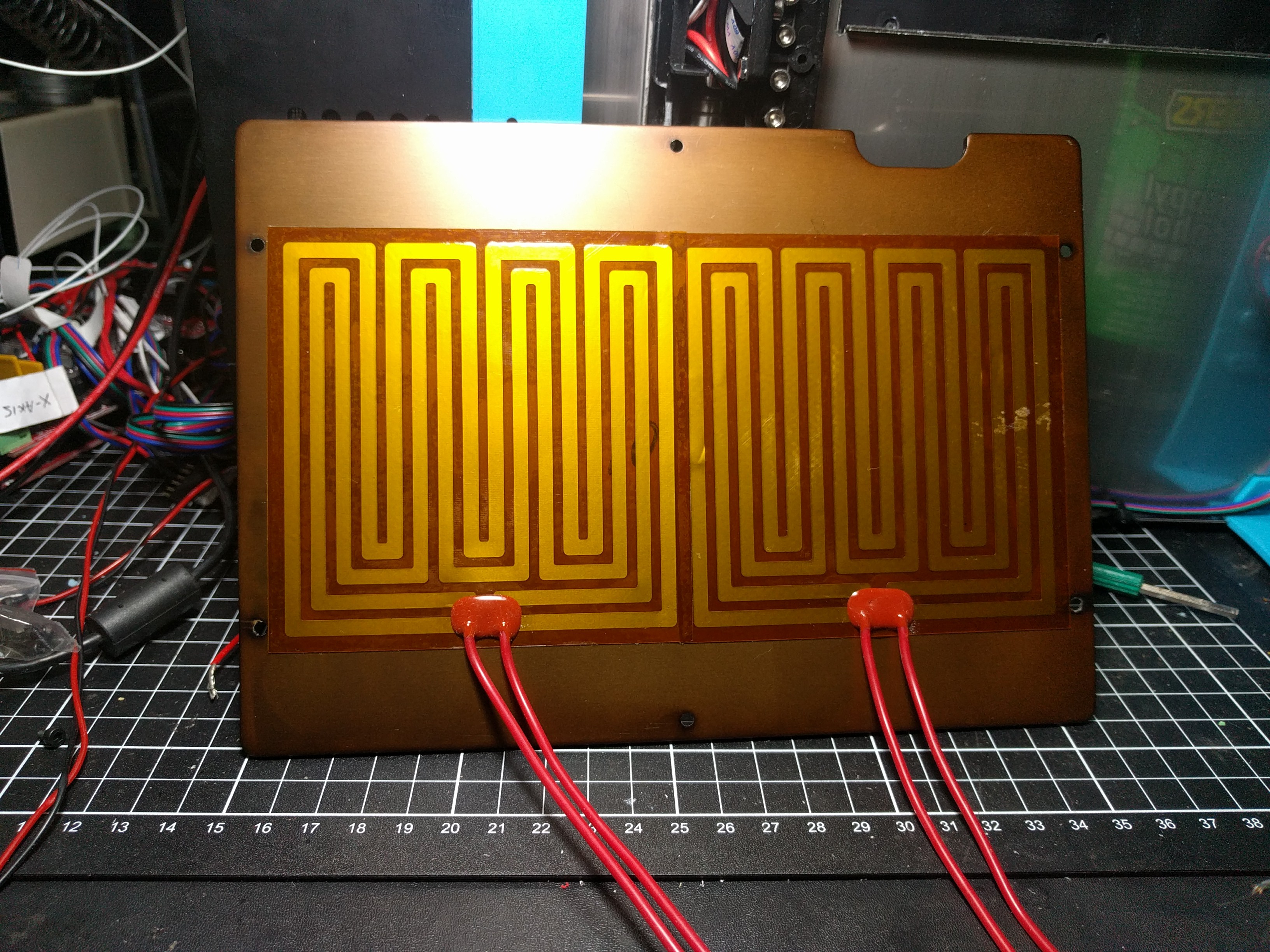
Above: A pair of stick-on heater pads underneath the aluminium plate that gives rigidity the build board. I used both glass and the Robox fibre glass surfaces successfully on top of this plate.
During this time I also wanted to tidy up the project as I felt I was making good headway and thought others may want to grab one of these printers and try saving it from the scrapheap as well. To do this I bought a GT2560 mother board and moved up to Marlin 2.x.x. This meant the likelyhood of a catastrophic short circuit was greatly reduced and, as it was RAMPS compatible, would not require a total rethink of the configuration or wiring.

Above: This was the state of the Mega2560+RAMPS1.4 board version, slightly dangerous? But fun hacking ;-) I could see a major setback on the horizon if I got short somewhere in here with a 30A supply.
Became...
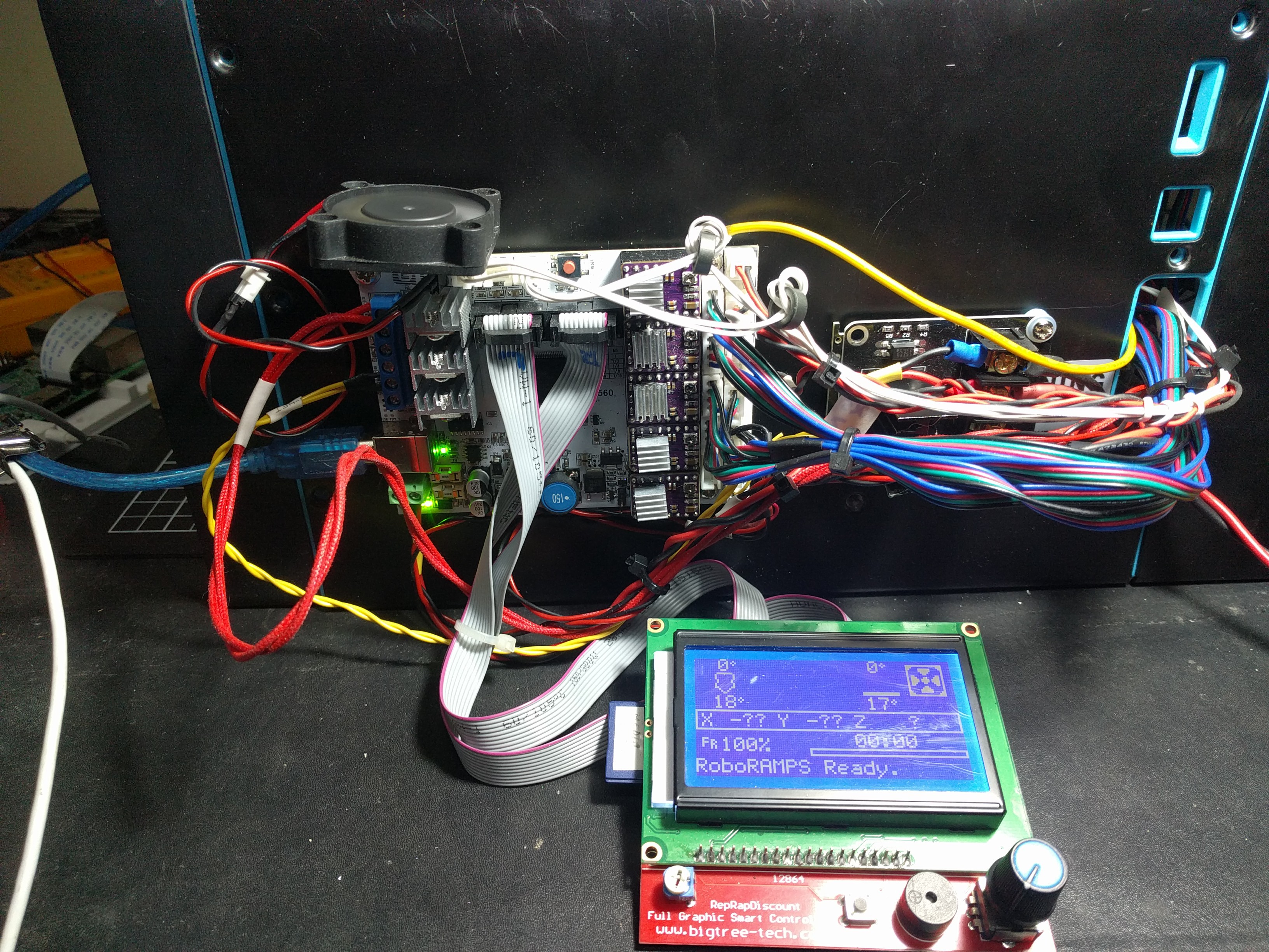
Above: The GT2560 board running Marlin. This was also eventually controlled through Cura+OctoPrint+RPi3B+Video. I thought of putting it inside the case but decided not to, for ease of maintenance, and why hide such awesome hacking!!!
..... later on, much more tidy. I was now getting reliable prints with good adhesion, structure and dimensions. One thing was nagging me though. The vertical feed of the filament into the print head meant the part height the printer could achieve was limited because the vertical Bowden tube and filament would begin to foul the plastic pull-down cover if it went above 40mm. This was a major limitation. I set about making a right angle heat block where the filament comes in at the back of the head parallel to the build board, and then turns a right angle to exit out of the vertical nozzle. I scoured the net looking for a commercial one and did not find one or anything I could adapt. I would have to make one. I got a block of aluminium and drilled holes into the block and tapped a throat thread in the side of the block, and a nozzle thread underneath. The bigger holes followed two preliminary intersecting 2mm pilot holes to make sure they connected (the larger holes did not connect up). A smaller hole was drilled for the thermistor and a larger hole for the 12V 40W standard heater. With redesign of the mounting wedge, it was altered to allow the Bowden tube, the heater wires, the thermistor wires to exit horizontally at the back of the hotend system.
The length of the effective thread into the heat block was small, maybe 4mm deep at the most. A 6mm tap was ground down so the usual lead in thread was removed and so it began with the full width thread. This was to try to get the thread as deep as the sides of the hole. To get this to tap quickly and perpendicular, the tap was mounted in a pedestal drill and the Aluminium heat block held with a vice clamp. The tap was lowered by the hand controls on the pedestal drill, and the tap rotated by using my hand on the chuck, and slight pressure downwards to make the tap cut in. This enabled a nearly perfectly aligned holes for the throat and nozzle at right angles to each other. No wobble to get started. It also made the most of the limited length of tap allowed for the nozzle and the throat. The nozzle and the throat tube were sealed inside the heat block by the end of the two of them "bottoming out" and the end of the nozzle for example was rammed into the aluminium block (this is why the drilling out of the threaded holes had to end in a cone and not have them join up. The slanting sides of the end of the threaded section made them self sealing - when sufficient force was added!!! No glue was required though it was considered.)
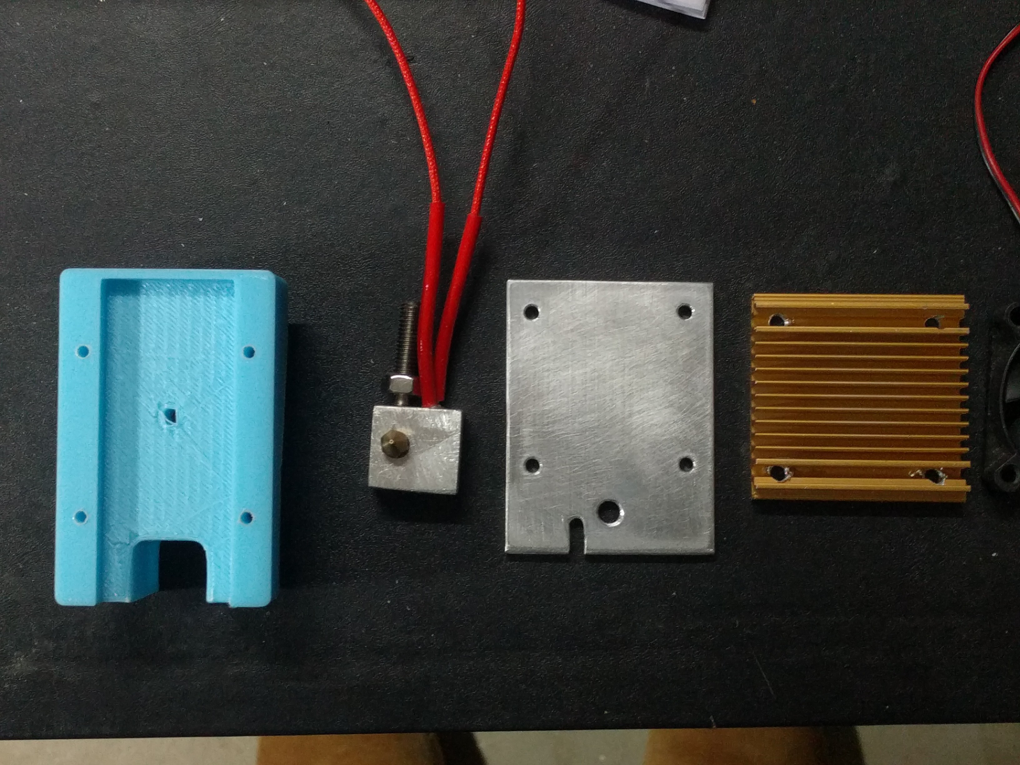
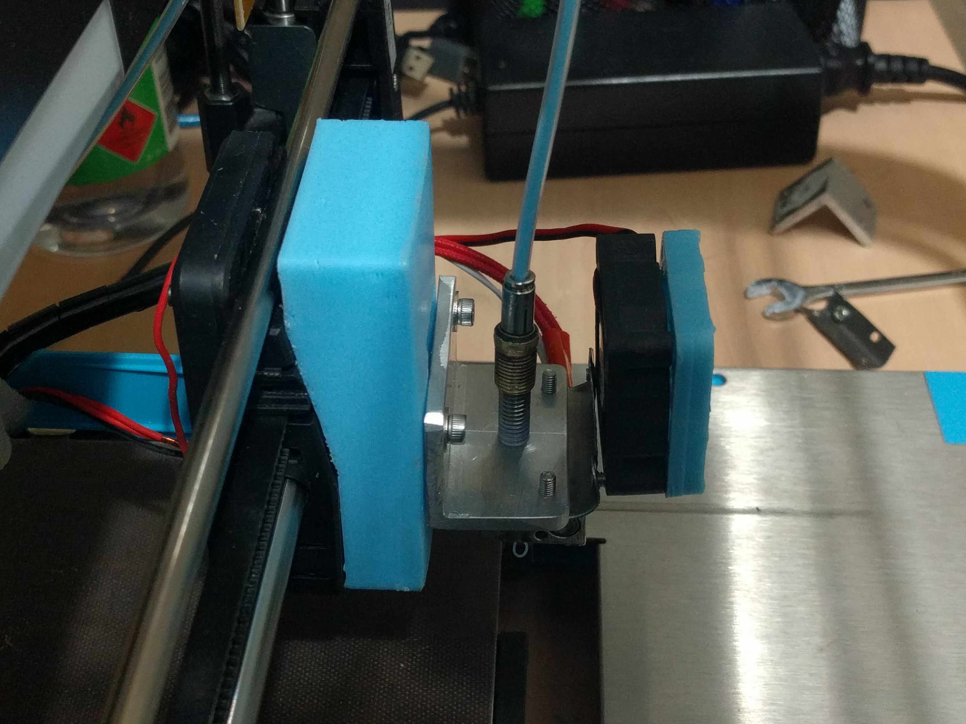
Above: RHS the old Pentium heatsink (C:1990?), Aluminium plate with mounting holes, 90degree heat block (throat vertical, nozzle pointing up), and the blue mounting wedge with slot for cables and ventilation at the back of the aluminium plate/heatsink.
I also introduced another problem at this time, and that was how was I going to mount a heat sink? I used a flat plate of Aluminium 3mm thick and bolted an old pentium heatsink onto it. The previous vertically mounted throatI could mount the fan over the top, with the fins horizontal so the cooling air would exit sideways and not confuse the work of the parts fan.

Above: The current design with rear entry filament and cables, plus illuminating part cooling fan.
The 30mm part cooling fan was given its own shroud and mounted to one side to direct air onto the part being built. Just as there are no 90degree heatblocks, the keen observer amongst you will see there are no standard 90degree silicon socks to go out and buy, so what remained of a standard one, hacked a bit, was clipped on with springy wire. An LED was mounted inside the shroud positioned at the center of the fan to illuminate the part being built. We all need a touch of bling in our lives.
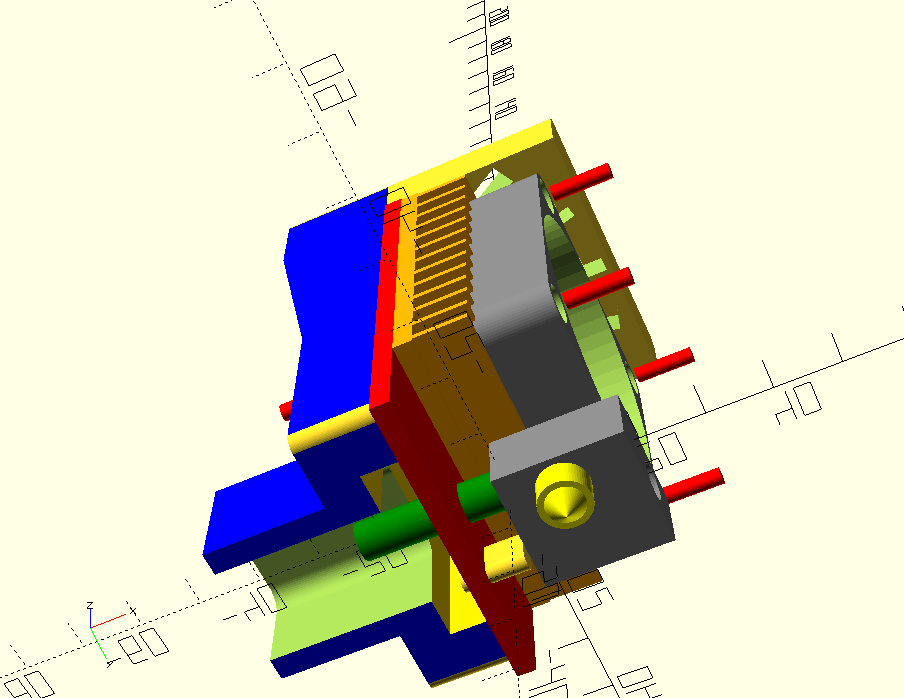
This is an Open SCAD render of the print head showing Fan and heat block in grey. Throat for the filament in green, nozzle on bright yellow, extra heat sink in gold, top-grill in light yellow, channel for wiring to the rear in light green. The main heat sink is the red slab running through the center.
PS There are many more details that have not been shared here. I am not confident to spend the time to do an exhaustive write up if there is no real interest by anybody else to try a similar thing. So this is just a summary to sound people out. Please contact me if you would like more information on any details I may have not explained all that well, or completely skipped over (eg springy build boards and auto-bed leveling). I can also make my two Marlin configuration files and OctoPrint scripts for filament wipe, auto bed levelling etc available if the demand exists.
And thanks for reading this far, it was a wild ride, but about 12months off and on of hard slog. Cheers, Rob