Some of the initial writeups of this quadruped robot were covered in logs for my related CAN Controlled Dual Closed-Loop Motor Controller project:
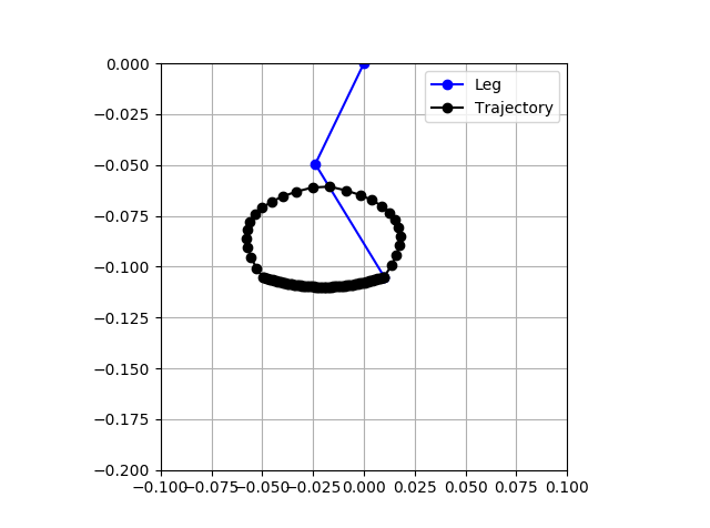
- First attempt at virtual model control
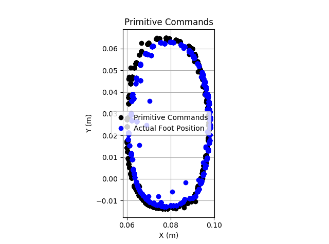
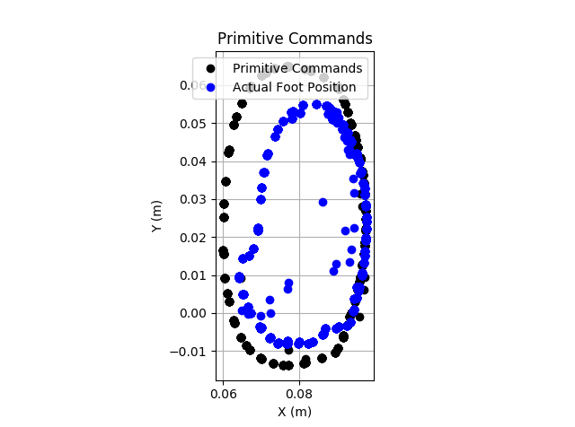
- Motion primitives and crawling
- Documentation of CAN messages, robot design, and motion playback
- Quadruped robot initial walking and gait analysis
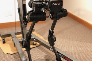
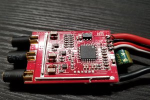
With this robot, I intend to reproduce a variety of advanced control techniques used in ambulatory robots. By having a motion co-processor for each leg, and by avoiding COTS hobby servos for control, I have full ability to design, implement, and tune controllers as I wish. I liken this architecture to the human nervous system, where some high-speed muscle control is done away from the brain. All of the motor controllers communicate over a 1Mbps CAN bus, so telemetry and commands are sent with low latency and high reliability.
First walking is shown below:
Logs:
 Anthrobotics
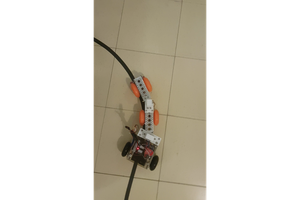
 Rupert Young