 Bud Bennett
The PIC program is written in assembler. It is pretty straightforward and can be explained in three flow charts.
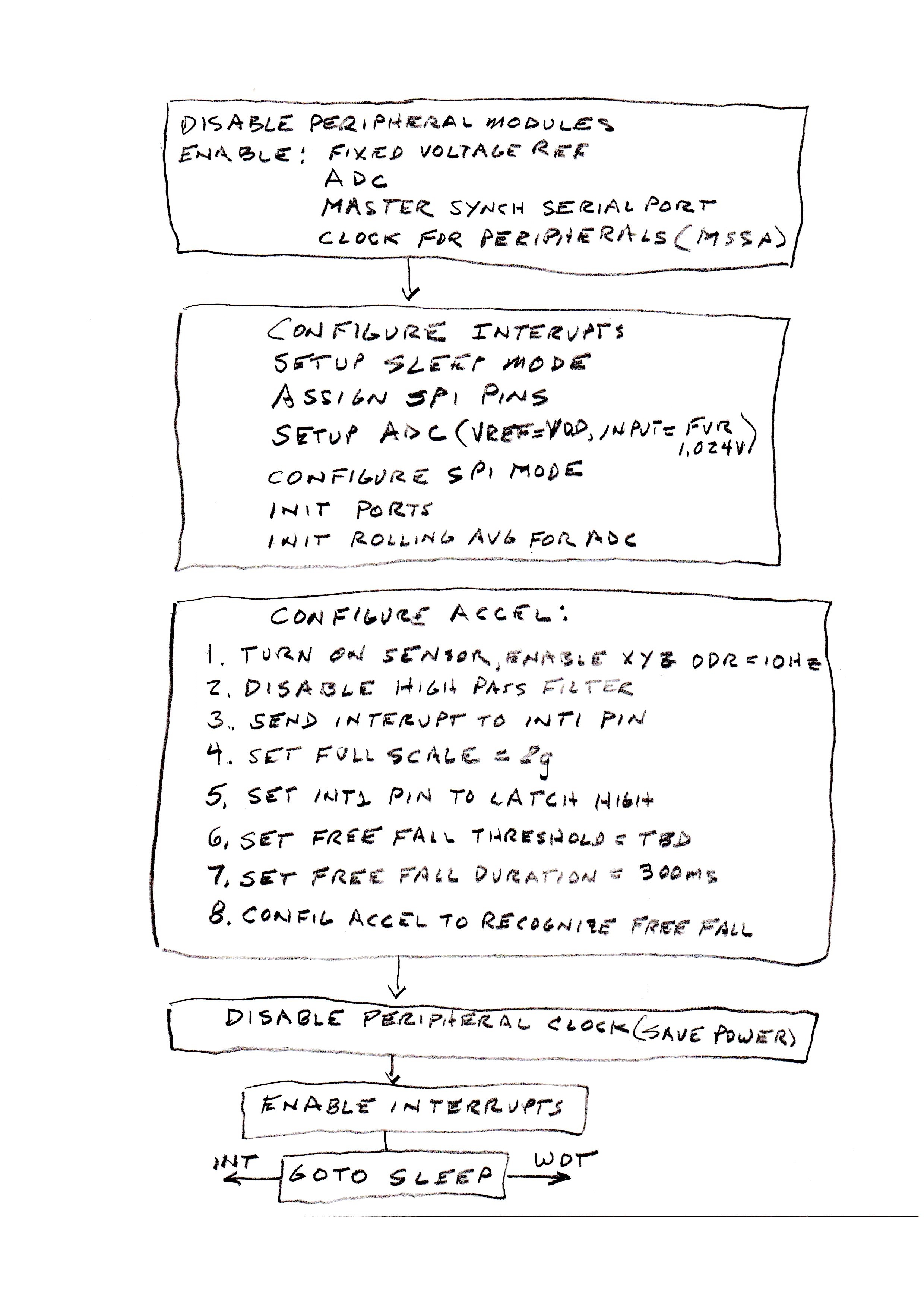 The chart above shows the steps necessary to configure the PIC and the accelerometer. Most of the peripheral modules are disabled. The only modules needed are the FVR, ADC, and MSSP (for the SPI interface). Then the modules are configured. The watchdog timer (WDT) is set to overflow after 264 seconds. The ADC is set to run on its own RC clock and place the 10-bit result so that the 8LSbs occupy the low byte of the two byte ADC result register. The SPI is set to match the protocol required by the accelerometer and is set to master mode since it controls the SPI clock (SCK). The I/O ports are set to digital with required input/output assignment. Lastly, the 8-byte ADC rolling average is zeroed out as a precaution.
The accelerometer is configured via the SPI interface to set an interrupt pin, INT1, when a free-fall event is detected. This sequence is right out of the application note for the LIS3DH, with a few parameters modified for this purpose. The peripheral clock is disabled to save power since it is only needed for the SPI interface.
The interrupts are enabled and the PIC goes to sleep, consuming only a fraction of 1µA. There are two ways to wake it from sleep: a WDT overflow every 264 seconds, or a interrupt on INT.
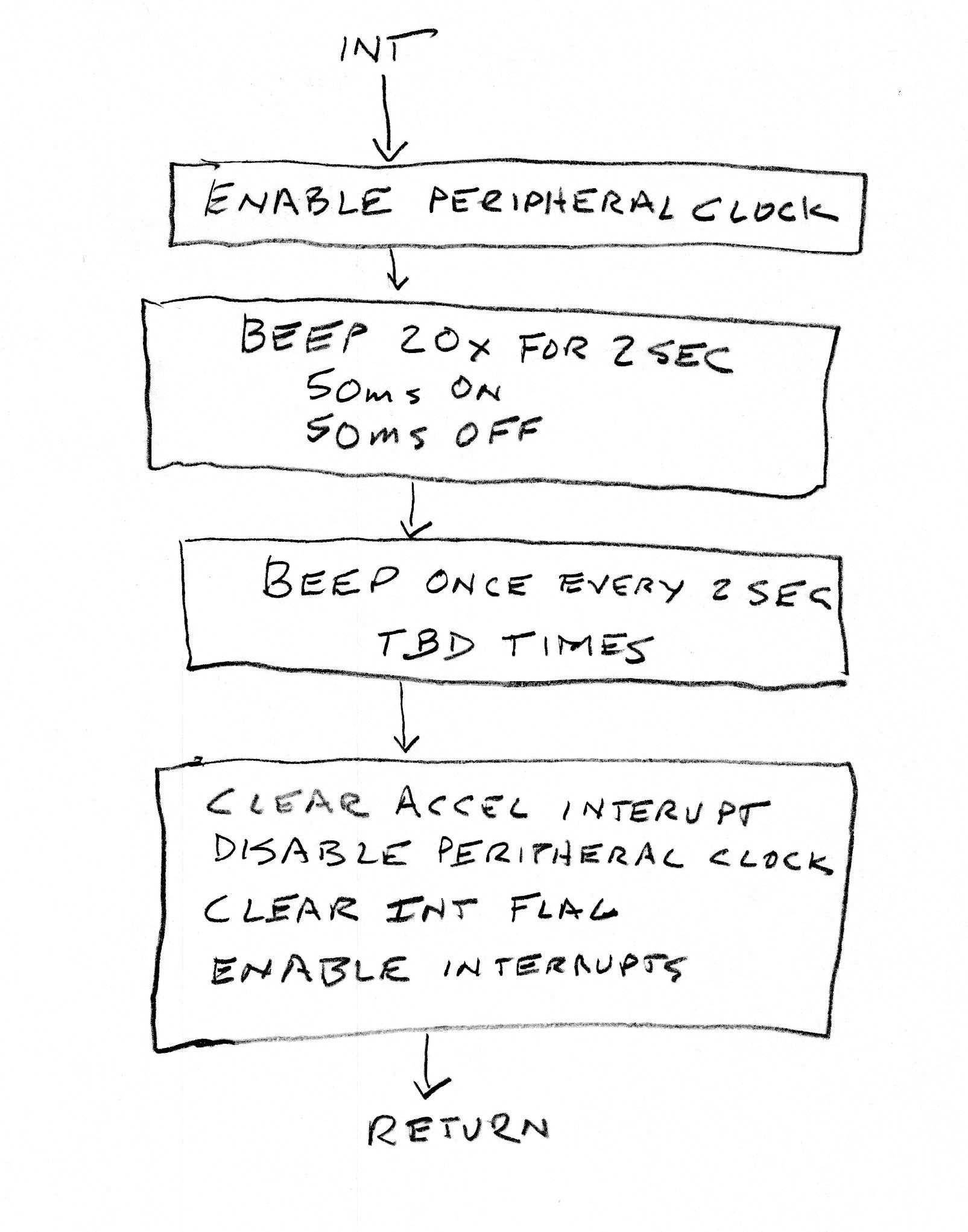 When the external INT pin is asserted the above routine wakes the PIC from sleep and executes. The beeper is exited in a series of 20 beeps (50ms on, 50ms off) for 2 seconds. Then there will be a 2 second pause and a 100ms beep, which repeats TBD times. After that the SPI is used to read data from the accelerometer to clear the interrupt event and unlatch the INT1 pin. PIC peripheral clocks are again disabled, the PIC interrupt flag is cleared and general interrupts are enabled. The routine returns to the running program -- most likely back to sleep.
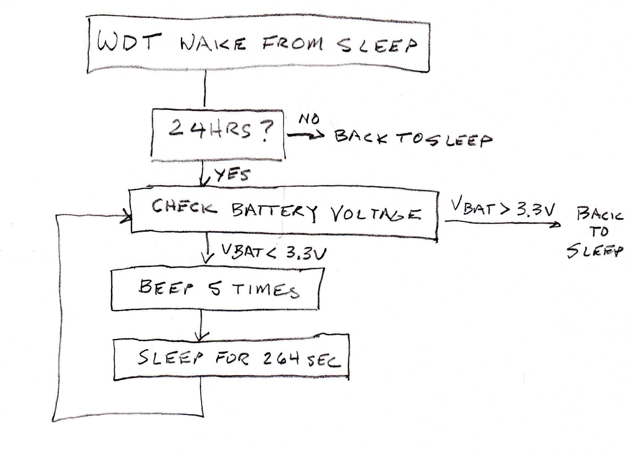 The WDT wakes up the PIC every 264 seconds. This routine counts out 24 hours before it checks the battery voltage. If the battery voltage is above 3.3V then the 24 hour timer is reset and the cycle begins again. If the battery voltage is below 3.3V then the PIC will beep 5 times (so as not to get it confused with a smoke detector) and go back to sleep until the WDT wakes it again to repeat the battery voltage check. I'm hoping that it won't do this at 2:00am.
I will post the entire MPLABX project to the files section when it is solidified.
Discussions
Become a Hackaday.io Member
Create an account to leave a comment. Already have an account? Log In.