Close
0%
0%

ROM-emulator

Emulate a small size ROM with a RAM and Arduino with Intel-HEX interface

Similar projects worth following
ROMemu is a combination of software and hardware that allows the usage of modern software development tools for simple, old style single board computer systems. It emulates an (EP)ROM programmer to the development software and an in-circuit ROM/RAM on the board. With WR* signal wiring it is accessible as RAM from the SBC.

The firmware is stable for some time (developed that with the prototype shield) and the hardware is just debugged on the v1.1 PCB.

ROMemu is a combination of software and hardware that allows the usage of modern software development tools for simple, old style single board computer systems (SBC). It emulates an EPROM programmer to the development software and an in-circuit RAM or ROM to the SBC.

The current version 1.1 uses an Arduino Mega 2560 with a shield containing a 32 kByte RAM-chip which is (partially) readable by the SBC-processor. The Arduino USB-connection is available as serial port to the development system. This allows to write Intel-hex data to the RAM.

ROMemu has two modes;
* SBC-mode where it is visible from the host computer and all Arduino pins (data, address, control) are tri-stated,
* Arduino-mode where it is isolated from the host and accessed by the Arduino. There is no synchronisation, but as long as the SBC isn't executing code from the emulated memory, the SBC shouldnt crash (mine didn't).

Technical details.

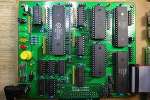
The basis of the ROMemu is an Arduino shield with a static RAM chip, fully connected to Arduino pins. Additionally three 74HCT244 connect address and control lines and a 74HCT245 connects the data lines of the host SBC. In this mode all Arduino lines are in tri-state mode. An extra signal, ArduinoOnline, can isolate the RAM from the SBC. An 74HCT02 74HCT27 controlling the 74HCT245 buffer makes sure the RAM is visible from the SBC while reading.

A short flat cable and an adapter board (pod) makes sure the RAM-chip signals are properly configured for the socket. The pod consists of two parts, an adapter between the RAM-pins and the pins provided by the socket and a set of pins for the socket. A pod configuration has to be made for each  socket type you want to support.

There is a github page at https://github.com/electrickery/ROM-emulator.

boardPatch1.1to1.2.jpg

Image with the board patch from 1.1 to 1.2

JPEG Image - 334.56 kB - 07/07/2021 at 06:59

Preview
Download

ROMemu0.5.ino.zip

Copy of the latest Arduino firmware (also on Github: https://github.com/electrickery/ROM-emulator)

Zip Archive - 3.49 kB - 12/24/2020 at 17:11

Download

emuPodKicad.zip

KiCAD files for the flatcable-socket board, with signal pads for patching. These are the 1.1 version files with some extra patch pads. Quite optional, as the pins are available too.

Zip Archive - 7.09 kB - 11/01/2020 at 14:37

Download

socketAdapter24.zip

Adapter to the 24-pin socket.

Zip Archive - 4.24 kB - 11/01/2020 at 14:37

Download

ROMemu1.2.zip

KiCAD files for the Arduino Mega 2560 shield. Fixed, but unproven.

Zip Archive - 28.25 kB - 11/01/2020 at 14:35

Download

View all 7 files

  • Minor updates

    fjkraan02/09/2023 at 09:24 0 comments

    The hardware and software works good enough for my needs, so only small updates:

    • Added combined echo and CR support for terminal mode,
    • Replaced the python3 romEmuFeed program with a newer version with better argument handling and made the tty port an argument too.

  • Arduino firmware and Python upload program update

    fjkraan02/05/2022 at 20:22 0 comments

    Updated the Arduino firmware and Python upload program, to reliable upload hex files produced by z80pack/z80asm. New versions at https://github.com/electrickery/ROM-emulator.

  • Improved 2716 emupod wiring

    fjkraan12/21/2021 at 14:19 0 comments


    2716
    28p cable header    24p socket header    remark
        1  A14                -             connect to GND
        2  A12                -             connect to GND
       20  CS*              18  CE*
       22  OE*              20  OE*
                            21  Vpp         connect to Vcc
       23  A11                -             connect to GND
       26  A13                -             connect to GND
       27  WE*                *             connect to Vcc or the WR* signal
       28  Vcc                -             not connected

  • ROMEmu assisted workflow

    fjkraan09/23/2021 at 16:19 0 comments

    My primary usage for the ROMEmu is writing and testing software for simple a Z80 SBC, the Multitech MicroProfessor MPF-I. The ROMEmu allows me to minimize the number of 'moving parts' while developing.

    One time setup:
    - connect the ROMEmu to the target system using a ROM or RAM socket mapped somewhere in the address space. For a startup ROM the SBC should be halted.

    Then it is mainly this iteration:

    - Edit and assemble some code for the destined address in the target memory space on the cross-assembler PC,
    - Upload the hex-intel file to the ROMEmu with the python script,
      For example 'python3 romEmuFeed.py lcdtest.hex 2000' The second argument compensates for the address difference between ROMEmu and target system
    - Execute the program in the ROMEmu memory. For the MPF-I this means 'RESET'; 'ADDR' 2000; 'GO',
    - Evaluate the program and restart at the edit step.

  • EmuPod & SocketAdapter information

    fjkraan08/02/2021 at 10:59 0 comments

    The EmuPod and SocketAdapter boards adapt the flat cable to a specific socket. The flatcable carries all signals from the 32kByte RAM, a 62256/D43256. The EmuPod transforms those to mimic the ROM signals. The SocketAdapter adapts to the physical socket form.

    Each target ROM has a different pin layout, so expect to reserve a set of these boards for each ROM. Not all pins will change, thanks to the JEDEC standard, but some will. The ROMEmu optionally also allows writing to the RAM if a write signal is available, complicating the configuration somewhat. Unused address lines are connected to GND, to address the lower area of the RAM. An unused write signal is tied to Vcc.

    Adding headers to the EmuPod:

    • the cable header is placed on the component side, the side with the white silk-screen markings
    • the socket adapter header is placed on the solder side. This to prevent the signals to be mirrored for the SocketAdapter. If you use a direct flatcable-socket adapter, then place the socket adapter header on the component side too.

    SocketAdapter remarks:

    • the header from the EmuPod is placed on the component side, the pins to the socket on the solder side. Make sure you use special socket headers with round pins, the usual flatcable header pins are to big. To protect the socket header pins from breaking off (and having you to resolder the header!) place at IC-socket on them. These are much easier to replace.

    Some EmuPod wiring configurations. Only the 2532 one is properly tested!

    Note: the cable header numbering used is the not the  standard Odd-Even order, but a Counter-Clock-Wise order, the same as used for I.C-sockets.

    This is for the 2532 EPROM socket (EmuPod24/SocketAdapter24):

    28p cable header    24p socket header    remark
        1  A14                -             connect to GND
        2  A12                -             connect to GND
       20  CS*              20  CE*
       22  OE*              22  OE*
       23  A11              18  A11
       26  A13                 -            connect to GND
       27  WE*                 *            connect to Vcc or the WR* signal
       28  Vcc                 -            not connected
         -                  23  Vpp         connect to Vcc

    This is for the 2732 EPROM socket (EmuPod24/SocketAdapter24):

    28p cable header    24p socket header    remark
        1  A14                -             connect to GND
        2  A12                -             connect to GND
       20  CS*              20  CE*
       22  OE*              22  OE*
       23  A11              21  A11
       26  A13                -             connect to GND
       27  WE*                *             connect to Vcc or the WR* signal
       28  Vcc                -             not connected
    

    This is for the 2716 EPROM socket (EmuPod24/SocketAdapter24):

    28p cable header    24p socket header    remark
        1  A14                -             connect to GND
        2  A12                -             connect to GND
       20  CS*              20  CE*
       22  OE*              22  OE*
       23  A11              21  A11
       26  A13                -             connect to GND
       27  WE*                *             connect to Vcc or the WR* signal
       28  Vcc                -             not connected
    

    This is for the 2764 EPROM socket (EmuPod28/SocketAdapter28):

    28p cable header    28p socket header    remark
        1  A14              -               connect to GND
       26  CE2                              not connected
          -               26 NC             not connected
       27  WE*              -               connect to Vcc or the WR* signal
                          27 PG*            not connected
    

    This is for the 27256 EPROM socket (EmuPod28/SocketAdapter28):

    28p cable header    28p socket header    remark
        1  A14              27  A14         
         -                   1  Vpp        not connected
       26  A13              26  A13
       27  WE*                *            connect to Vcc or the WR* signal
    

    This is for the 62256 RAM socket (EmuPod28/SocketAdapter28):

    28p cable header    28p socket header    remark
        1  A14              27  A14         
       26  A13              26  A13
       27  WE*              27  WR*
    

  • Fix for ROM Emulator 1.1 Mega boards

    fjkraan07/07/2021 at 06:58 0 comments

    The 1.1 board did seem to work in some conditions, but wasn't really universally usable. This is a fix for the board, making it compatible with the 1.3 design. I didn't need more boards, so haven't really ordered and build any 1.2 or 1.3 for testing. The modification for 1.1 described here does work.

    - replace the 74LS02 at U2 with a 74LS27
    - cut trace to U2-1
    - cut trace to U2-2 (component side)
    - cut trace between U2-6 and U2-7
    - cut both traces to U2-12
    - cut trace between U2-8 and U2-9
    - connect U2-9, U2-10, U2-11 to U2-7 (unused port)
    - connect U2-1, U2-2, U2-13 to U2-6
    - connect U2-4 to U6-7 (H1, buffered board OE*)
    - connect U2-5 to U5-1 (H0, buffered board CS*)
    - connect U2-12 to U3-19 (board read)

    See the boardPatch1.1to1.2.jpg image

  • ROM-emulator application

    fjkraan12/26/2020 at 21:08 0 comments

    An usage for the ROM-emulator just went live at GitHub: https://github.com/electrickery/Z80SerialMonitor

View all 7 project logs

Enjoy this project?

Share

Discussions

Similar Projects

Does this project spark your interest?

Become a member to follow this project and never miss any updates