Close
0%
0%

A first FPGA project - SPI

How to create a SPI bus on an FPGA, and send data back and forth between a microcontroller and a FPGA

Public Chat
Similar projects worth following
772 views
0 followers
I wanted to learn how to program a FPGA. So, I got a Max10 eval board, a USB blaster, and a 3.3V ATMEGA256RFR2 xplained board.

I wanted to do some projects with a FPGA.  Starting out was a little rough, so here are my steps to help you save time.

1) Get the hardware

I got the Max10 evaluation board.  What I didn't realize when I ordered the board is that the USB cable is for powering the board only.  There is no programmer.  The board has a power supply, clock, some LEDs and breakout of the pins.

I got the USB blaster, the cheaper version from Terasic.  This lets you program the FPGA.

I had an ATMEGA256RFR2 evaluation board.  This board runs the controller at 3.3V, so it is compatible with the Max10 evaluation board.  This board is nice because you can program the ATMEGA256RFR2 over usb, and also shows up as a COM port, so you can communicate with the microprocessor from a PC.

Here is the block diagram.  The PC connects to the ATMEGA256RFR2 by serial port (serial over USB), and then the ATMEGA256RFR2 will connect to the Max10 FPGA using SPI.

2) Write the software

For the ATMEGA256RFR2, I wrote a program that lets you use the microprocessor from a command-line like perspective.  I'll put the code in a post, but the main idea is that from the PC, you can just read/write the registers of the ATMEGA256RFR2.  I wrote and programmed the ATMEGA256RFR2 using Atmel Studio 7.0.

For the Max10, you need to install Quartus (Quartus Prime 20.1) Lite Edition.  Once you have it installed, you need to create a new, blank project for the target FPGA.  In my case, you need to read the part number off of the chip, 10M08SAE144C8G.  I'll post the verilog in a post.

3) Run and test

I connect to the ATMEGA256RFR2 using Tera term.  Then, I send bytes over SPI using the sequence of register read and writes.  The FPGA responds with a simple byte response.
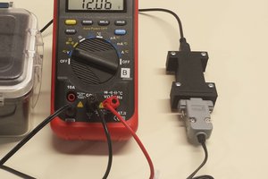
  • 1 × EK-10M08E144 Max 10 evaluation board
  • 1 × ATMEGA256RFR2-XPRO atmega256RFR2 evaluation board
  • 1 × P0302 Terasic USB blaster

  • Main.h

    sciencedude199011/17/2020 at 16:12 0 comments

    #ifndef MAIN_H_
    #define MAIN_H_
    
    // Serial port stuff
    #include <string.h>
    #include <stdio.h>
    
    // Printing a string to the serial port
    void print_serial(const char * const print_string);
    
    // Given an input array, process the command
    void go_process_command();
    
    #endif // MAIN_H_

  • ATMEGA256RFR2 project code

    sciencedude199011/02/2020 at 03:47 0 comments

    Here is the code for the microcontroller (ATMEGA256RFR2, running at 3.3 V)

    #include <avr/io.h>
    // LOW.CLKDIV8 is unchecked, and LOW.CKSEL_SUT is Transceiver Oscillator; Start-up time: 16K CK +  65 ms
    #define F_CPU 16000000UL
    #include <util/delay.h>
    #include <avr/interrupt.h>
    #include "main.h"
    
    // Place to store a string for USART communication
    static char temp_string[64];
    // Simple routine to output a serial string to the UART
    void print_serial(const char * const print_string) {
        uint8_t temp = 0;
        
        while (temp < strlen(print_string)) {
            if ((UCSR1A & 0x20) == 0) {
                // Do nothing
                _delay_us(10);
            }
            else {
                // Send a byte
                UDR1 = (uint8_t) print_string[temp];
                temp = temp + 1;
            }
        }
        
        // Send ASCII 13 and 10
        temp = 0;
        while (temp < 2) {
            if ((UCSR1A & 0x20) == 0) {
                // Do nothing
                _delay_us(10);
            }
            else {
                if (temp == 0) {
                    UDR1 = 13;
                }
                
                if (temp == 1) {
                    UDR1 = 10;
                }
                temp = temp + 1;
            }
        }
    }
    
    // Place to store the user input
    static uint8_t rx_in_buffer[64];
    // The count of user input
    static uint8_t rx_in_buffer_count = 0;
    
    ISR(USART1_RX_vect) {
    
        // Read the character from the buffer
        uint8_t temp = UDR1;
        
        // Put the character in the buffer
        rx_in_buffer[rx_in_buffer_count] = temp;
        // Increment the count
        rx_in_buffer_count = rx_in_buffer_count + 1;
        // Count has to be less than 63
        if (rx_in_buffer_count > 63) {
            rx_in_buffer_count = 63;
        }
    
        // If the character is carriage return, process the command
        if (temp == 13) {
            go_process_command();
        }
    }
    
    void go_process_command() {
        // Print some characters in the buffer
        //snprintf(temp_string, 64, "Rx: %d, %d, %d, %d, %d, %d", rx_in_buffer[0], rx_in_buffer[1], rx_in_buffer[2], rx_in_buffer[3], rx_in_buffer[4], rx_in_buffer[5]);
        //print_serial(temp_string);
        
        // The read command
        if ((rx_in_buffer[0] == 114) || (rx_in_buffer[0] == 82)) { // The read command, r or R, expect decimal, for example, expect r72 to read 0x48, OCR0B
            //print_serial("r/R");
            
            // The location of the carriage return
            uint8_t ind_13 = 0;
            
            // Find character 13
            for (uint8_t ii = 1; ii < 64; ii++) {
                if (rx_in_buffer[ii] == 13) {
                    ind_13 = ii;
                    break;
                }
            }
            // Where character 13 was found
            //snprintf(temp_string, 64, "Char13: %d", ind_13);
            //print_serial(temp_string);
            
            // For processing the register address (convert ASCII characters to addr)
            uint8_t found_it = 0;
            uint16_t addr = 0;
            uint16_t pow_10 = 1;
            
            // If ind_13 was found, build up addr
            if (ind_13 > 1) {
                for (uint8_t ii = (ind_13 - 1); ii > 0; ii--) {
                    if ((rx_in_buffer[ii] >= 48) || (rx_in_buffer[ii] <= 57)) {
                        addr = addr + (rx_in_buffer[ii] - 48) * pow_10;
                        pow_10 = pow_10 * 10;
                        found_it = 1;
                    }
                    else { // Unexpected character
                        found_it = 0;
                        break;
                    }
                }
            }
            // Print the address and whether the parsing was as expected
            //snprintf(temp_string, 64, "addr: %u, found_it: %d", addr, found_it);
            //print_serial(temp_string);
            
            // Print the register value
            if (found_it == 1) {
                volatile uint8_t * reg_addr = (uint8_t *) addr;
                uint8_t temp_value = *reg_addr;
                snprintf(temp_string, 64, "Reg: %u = %d, %x", addr, temp_value, temp_value);
                print_serial(temp_string);
            }
        }    
        else if ((rx_in_buffer[0] == 119) || (rx_in_buffer[0] == 87)) { // The write command, w or W, for example, expect w72=4
            //print_serial("w/W");
            
            // The location of the carriage return
            uint8_t ind_13 = 0;
            // Find character 13, carriage return
            for (uint8_t ii = 1; ii < 64; ii++) {
                if (rx_in_buffer[ii] == 13) {
                    ind_13 = ii;
                    break;
                }
            }
            
            // The location of the =
            uint8_t ind_eq = 0;
            for (uint8_t ii = 1; ii < 64; ii++) {
                if (rx_in_buffer[ii] == 61) {
                    ind_eq = ii;
                    break;
                }
            }
            
            // Where character = and 13 were found
            //snprintf(temp_string, 64, "Char=: %d, 13: %d", ind_eq, ind_13);
            //print_serial(temp_string);
            
            if ((ind_eq > 1) && ((ind_eq + 1) < ind_13)) {
                // For processing the register address (convert ASCII characters to addr)
                uint8_t found_it = 0;
                uint16_t addr = 0;
                uint16_t pow_10 = 1;
                // Get the register address
                for (uint8_t ii = (ind_eq -...
    Read more »

  • Code for the FPGA

    sciencedude199010/30/2020 at 18:01 0 comments

    Here is the code for the FPGA.  I noted the pin numbers in at the top...

    // Main module - monitor the ports from the microcontroller
    module spi_micro_test(
    	input wire clk, // 50 MHz clock, pin 27
    	input wire bar_ss, // SPI chip select, pin 93
    	input wire mosi, // SPI master output, pin 92
    	input wire sck, // SPI clock, pin 99
    	output wire miso, // SPI sidekick output, pin 101
    	output wire led1, // LED1 pin 132
    	output wire led2, // LED2 pin 134
    	output wire led3, // LED3 pin 135
    	output wire led4, // LED4 pin 140
    	output wire led5); // LED5 pin 141
    
    //////	
    // Observe the serial clock
    reg [2:0] sck_r;
    initial begin
    	sck_r <= 3'b000;
    end
    always @ (posedge clk) begin
    	sck_r <= {sck_r[1:0], sck};
    end
    
    // Detect the rising edge
    wire sck_risingedge = (sck_r[2:1]==2'b01);
    // Detect the falling edge
    wire sck_fallingedge = (sck_r[2:1]==2'b10);
    
    //////
    // Observe the mosi wire
    reg [1:0] mosi_r;
    
    always @ (posedge clk) begin
    	mosi_r <= {mosi_r[0], mosi};
    end
    // The mosi data
    wire mosi_data = mosi_r[1];
    
    //////
    // Observe bar_ss
    reg[2:0] bar_ss_r;
    initial begin
    	bar_ss_r <= 3'b111;
    end
    
    always @ (posedge clk) begin
    	bar_ss_r <= {bar_ss_r[1:0], bar_ss};
    end
    
    // Detect the rising edge
    // wire bar_ss_risingedge = (bar_ss_r[2:1]==2'b01);
    // Detect the falling edge
    wire bar_ss_fallingedge = (bar_ss_r[2:1]==2'b10);
    // Observation of bar_ss
    wire bar_ss_observe = bar_ss_r[1];
    
    //////
    // Place to store input data
    // reg data_ready;
    reg [2:0] bit_count;
    reg [7:0] data_rx;
    
    //////
    // Place to store the output data
    reg [7:0] data_tx;
    
    initial begin
    	data_tx <= 8'b01100101;
    end
    
    // Output is tristate, until bar_ss_observe becomes 0
    assign miso = (!bar_ss_observe) ? data_tx[7] : 1'bz;
    
    // Capture the value of the bar_ss input from the microcontroller
    always @(posedge clk) begin
    	if (bar_ss_fallingedge == 1'b1) begin
    		// On the falling edge of bar_ss, clear data ready 
    		// data_ready <= 1'b0;
    		bit_count <= 3'b000;
    	end else if ((bar_ss_observe == 1'b0) && (sck_risingedge == 1'b1)) begin
    		// If bar_ss is low and on the rising edge, bring in a bit
    		bit_count <= bit_count + 3'b001;
    		data_rx <= {data_rx[6:0], mosi_data};
    	end else if ((bar_ss_observe == 1'b0) && (sck_fallingedge == 1'b1)) begin
    		data_tx <= {data_tx[6:0], data_tx[7]};
    	end
    	
    end
    
    // Set the LED outputs
    assign led1 = data_rx[0];
    assign led2 = data_rx[1];
    assign led3 = data_rx[2];
    assign led4 = data_rx[3];
    assign led5 = bar_ss_observe;
    
    endmodule

View all 3 project logs

Enjoy this project?

Share

Discussions

sciencedude1990 wrote 11/09/2020 at 22:47 point

If you want - check out the next step which was to create a register map and PWM outputs.

https://hackaday.io/project/175677-super-custom-pwm-fpga

  Are you sure? yes | no

Similar Projects

Does this project spark your interest?

Become a member to follow this project and never miss any updates